Page Contents
Minox AG 1 Flash Unit for Minox A/IIIs
Since 1954, Minox A/IIIs had a synchronized flash connection. However, a flash unit had to be purchased from a third-party manufacturer. A sync cable was required.
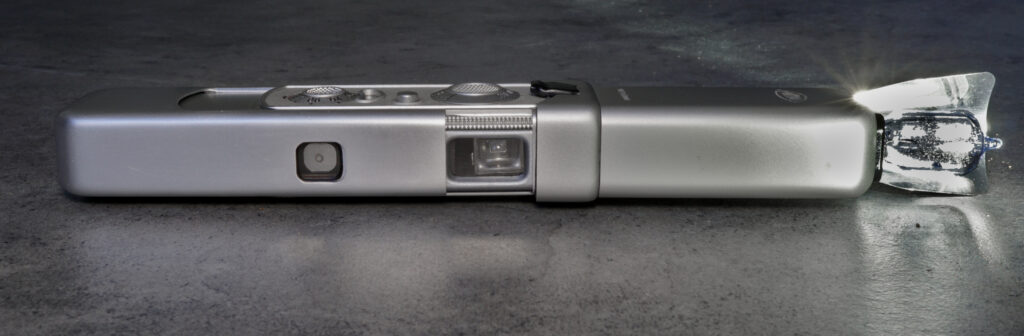
In 1960, Minox GmbH introduced the AG 1 flash unit, a small revolution in the realm of subminiature photography. Designed as the perfect companion to the iconic Minox A camera, this compact accessory combined technical sophistication with the precision synonymous with Minox. It greatly expanded the capabilities of the Minox A.
When the device came onto the market, it was probably the smallest flash unit in the world. At the same time, it has an impressive light output . When closed, no reflector disturbs its shape, which corresponds exactly to the Minox camera. There is also no need for a cable or separate clip-on shoe. The flash unit is plugged on the camera and is immediately ready for use.
The small reflector of the Minox flash unit has one major advantage: it provides a soft light.
The Minox A and Its Era
The Minox A, first launched after World War II and produced until 1969, was already a technical marvel. Measuring just 82 x 28 x 16 mm and weighing a mere 70 grams, it was an ideal camera for discreet, portable photography. Its Complan lens (1:3.5/15 mm) and shutter adjustable from 1/2 to 1/1000 seconds offered impressive flexibility. However, until 1954, it lacked a crucial feature: a flash synchronization contact. This was later added, and by 1960, the AG 1 flash unit arrived as a tailored solution.
Overview
The AG 1 flash unit was specifically engineered for the Minox A, utilizing the AG flash bulbs (introduced 1958) – the smallest of their kind. In relation to their size, these flash bulbs have a high lighting power – even compared to modern electronic flashes. With a flat glass base and a guide number of approximately 25/82 1 , these bulbs provided a compact yet effective light source.
The flash unit was plugged directly onto the Minox’s sync contact, eliminating the need for a cable. This was, of course, more convenient, faster, and space-saving. The design was minimalist yet functional – quintessential Minox.
Operation
Operation is straightforward: Mount the device, insert a flash bulb, extend the reflector and set the camera to a shutter speed of 1/20 second:
Here are the most important phases from the video above. The actual firing of the flash, shown here in still photos, takes about half a second.
The camera must be set to an exposure time of 1/20 s for flash photography. The flash lights up for a total of half a second, i.e. 10 times longer. But there is only a short period of time in which it is at its brightest (picture 3). The camera therefore knows exactly when to fire the flash after pressing the shutter release button so that the shutter is fully open at the brightest moment. This is called flash synchronization. The details are explained further down in this article.
At the end, the flash bulb is still very hot. This is why the flash unit has an ejector that automatically ejects the flash bulb when the reflector is retracted. This can be seen clearly at the end of the video. It is important not to drop the hot bulb on heat-sensitive surfaces.
Caution: only trigger the flash when the reflector is extended! It also serves as a protective shield for your face against the enormous heat of the flash.
A new flash bulb inserted in the device can very slowly discharge the battery. So do not store the flash with an unused bulb for months.
Kasemeier2 gives the following distance recommendations for Minox (f3.5) with AG 1 bulbs:
| film speed | distance |
|---|---|
| ISO 13…14 | 1 … 4 m |
| ISO 40 | 1.5 … 6 m |
| ISO 100 | 2 … 8 m |
| ISO 200 | 3 … 12 m |
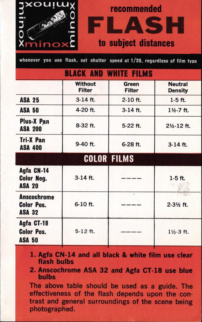
US Minox Processing Laboratories have specified the following distances in their flyer. No information is given on the flash bulbs. As there were only AG 1 and AG 1B at that time, I assume that AG 1 was meant for black and white films and AG 1B for color films:
Technical Ingenuity of the Minox AG 1
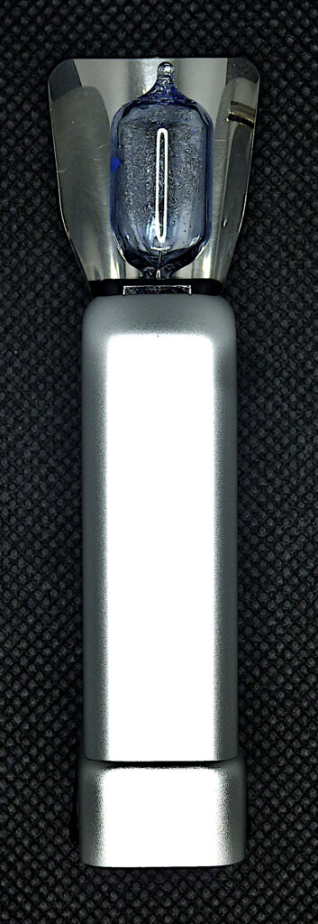
The AG bulb
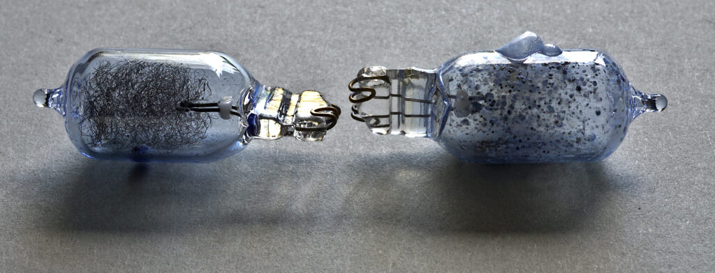
The photo above shows a new and a burnt-out AG 3B (“Blue”) flash bulb. You can clearly see the flammable filaments made of metal wire on the left. On the right you can see burning residues inside and the blue plastic layer surrounding the glass bulb, which has been blown up by the heat. The two contact wires for ignition can be seen on the glass bases.
Design
Flash bulbs feature a sealed glass enclosure housing either a slender wire or a thin sheet composed of zirconium. The interior of the enclosure is filled with oxygen at a low pressure. Electrical connections, or electrodes, are linked to the wire or sheet, enabling the passage of electrical current. To achieve maximum miniaturization, AG (“All Glass”) bulbs connected electrodes directly through the bottom glass, dispensing with the standard base. AG bulbs manufactured by General Electric were first sold in 1958.
Safety aspects
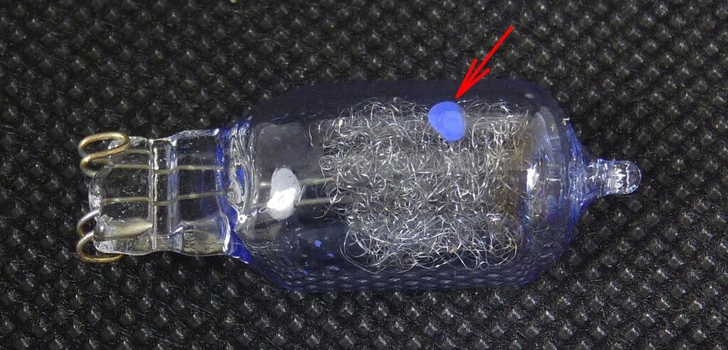
An unused, intact AG flash bulb can be recognized by the blue dot on the glass. It indicates that the bulb is still airtight. A key factor in light bulb explosions is air infiltration through a damaged base seal. This leads to elevated internal gas pressure, and the subsequent heat-induced expansion can cause the bulb to burst. To mitigate this risk, manufacturers employ a color-changing indicator, specifically a blue cobalt chloride spot that turns pink upon air exposure. Cobalt chloride changes its color from blue to pink with increasing humidity. Any bulb displaying a pink spot should be considered defective and removed from service.
Types
There were different variants of the AG flash bulb type. They differ in color temperature and amount of light:
| type | light output | lighting time | color temperature | bulb color | flash guide number |
|---|---|---|---|---|---|
| AG 1 | 7500 | ? | 4000 | clear | 25/82 |
| AG 1B | 5500 | ? | 5500 | blue | 22/72 |
| AG 3B | 7500 | 15 | 5500 | blue | 25/82 |
Light output: lumen seconds
Lighting time: milliseconds
Color temperature: ° Kelvin
Flash guide number: ISO 50, 1/25 s, distance in m / feet
Note the high flash guide numbers!
Synchronisation with the camera
Features of the flash bulb
Unlike modern electronic flashes, which fire almost instantaneously, flash bulbs have a “warm-up” period (typically 20 milliseconds). This warm-up time means the flash must be triggered before the shutter is fully open to ensure the maximum amount of light reaches the film during the exposure. The Minox camera uses the so called M sync synchronization method for flash synchronisation and needs the appropriate light bulbs (AG 1 or similar).
The “M” in “M sync” stands for “medium,” indicating the medium burn time of flash bulbs. M synchronization is designed to trigger the flash a short time before the shutter fully opens.
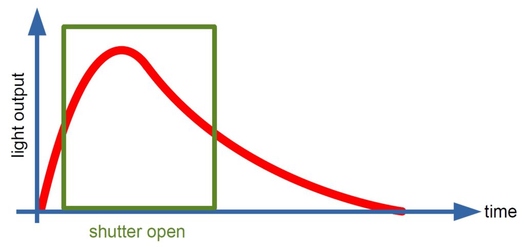
The next sequence of images shows what the above diagram looks like in reality. It starts with image 1 at 0 milliseconds with the ignition of the bulb and ends with the extinction. You can clearly see that the bulb – as in the diagram – reaches maximum brightness very quickly. Afterwards, the brightness decreases only slowly. The images are extracted from the video shown above. The second and third image are overexposed and represent the maximum brightness of the flash bulb:
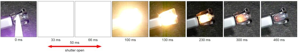
The burning process of the AG 3B bulb used here takes about half a second (460 ms). The bulb gives its maximum brightness for 66 milliseconds starting at 33 ms. The recommended exposure time for the Minox is 1/20 s, i.e. 50 milliseconds with shutter open.
The following two pictures prove that the synchronization of camera and flash works. I have enlarged the lens from still photo 1 of the above sequence (at 0 ms, the flash has just fired) and still photo 4 (100 ms, the flash has just left the phase of maximum brightness). Picture 1 shows the cocked, closed shutter, recognizable on a Minox by the circle in the middle of the shutter blade. Picture 4 shows the closed shutter without the circle, i.e. after closing the lens:
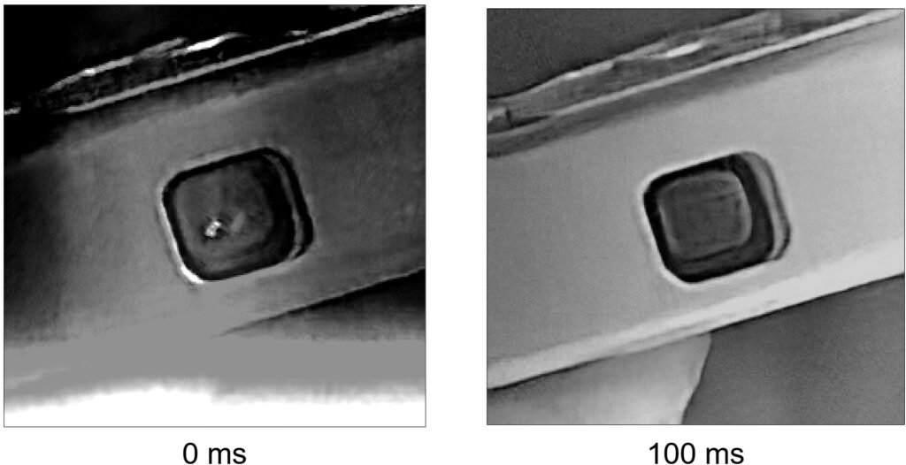
From this it can be concluded that the shutter was opened exactly during the brightest phase.
Synchronization mechanism of the camera
The flash is fired mechanically by the shutter in the camera using M synchronization. M synchronization is a flash synchronization method designed for cameras using leaf shutters, necessary because flash bulbs require a certain amount of time to reach their peak brightness. This only works with the Minox at 1/20 s shutter speed (or longer). This value must therefore be set.
How does the camera do the synchronisation? A mechanical linkage is used to press a contact plate against the two contacts of the flash connector approx. 20 ms before the shutter’s opening blade opens the lens. This closes the switch S in the electrical circuit of the flash unit.
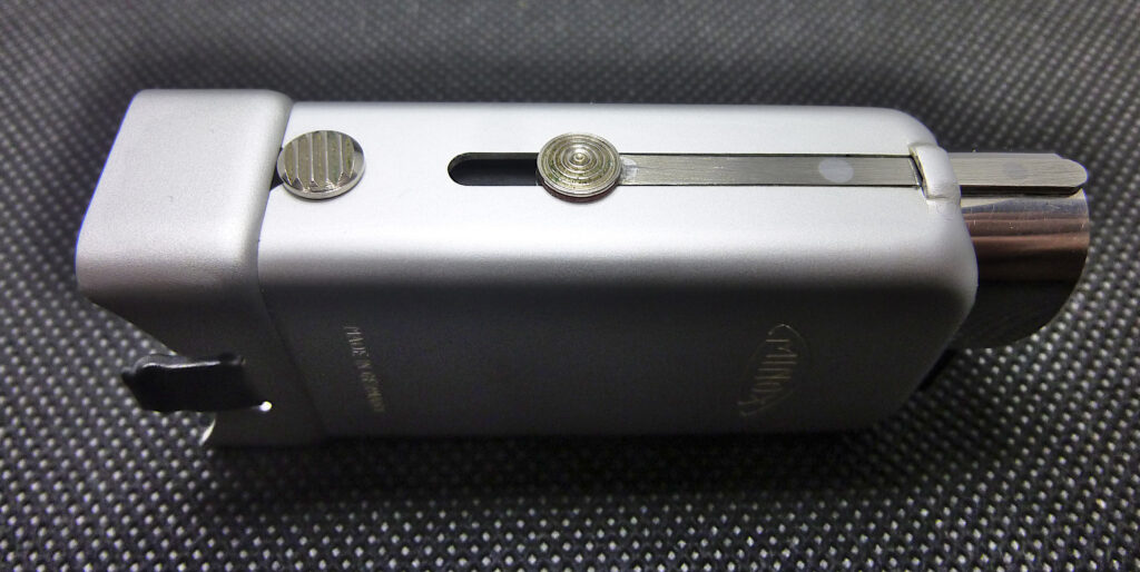
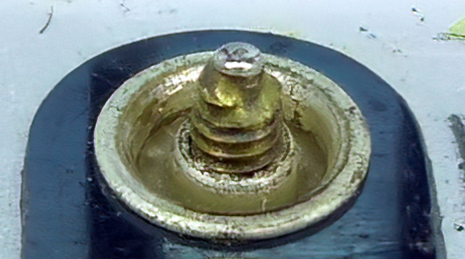
As the switch for triggering the flash is located in the camera, two contacts must be routed from the flash unit into the camera. One contact runs via the housing of the camera, the other via an insulated cable from the flash unit via a socket/plug connection. We can see this connection here:
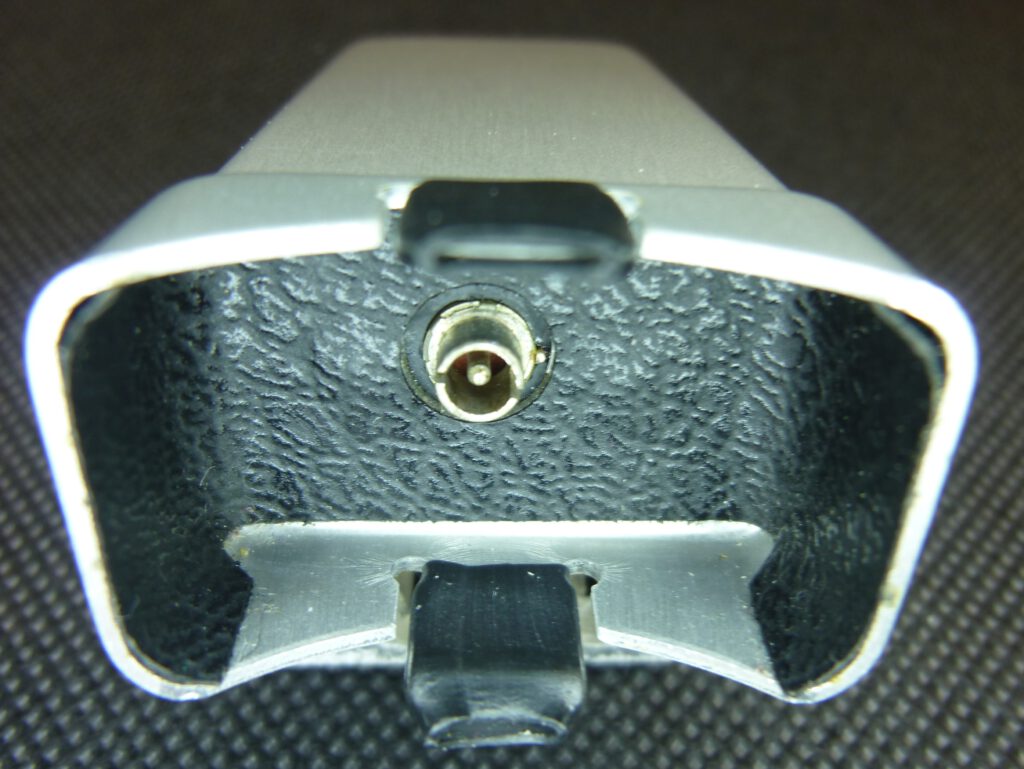
Ring outside: camera housing, pin inside: insulated wire
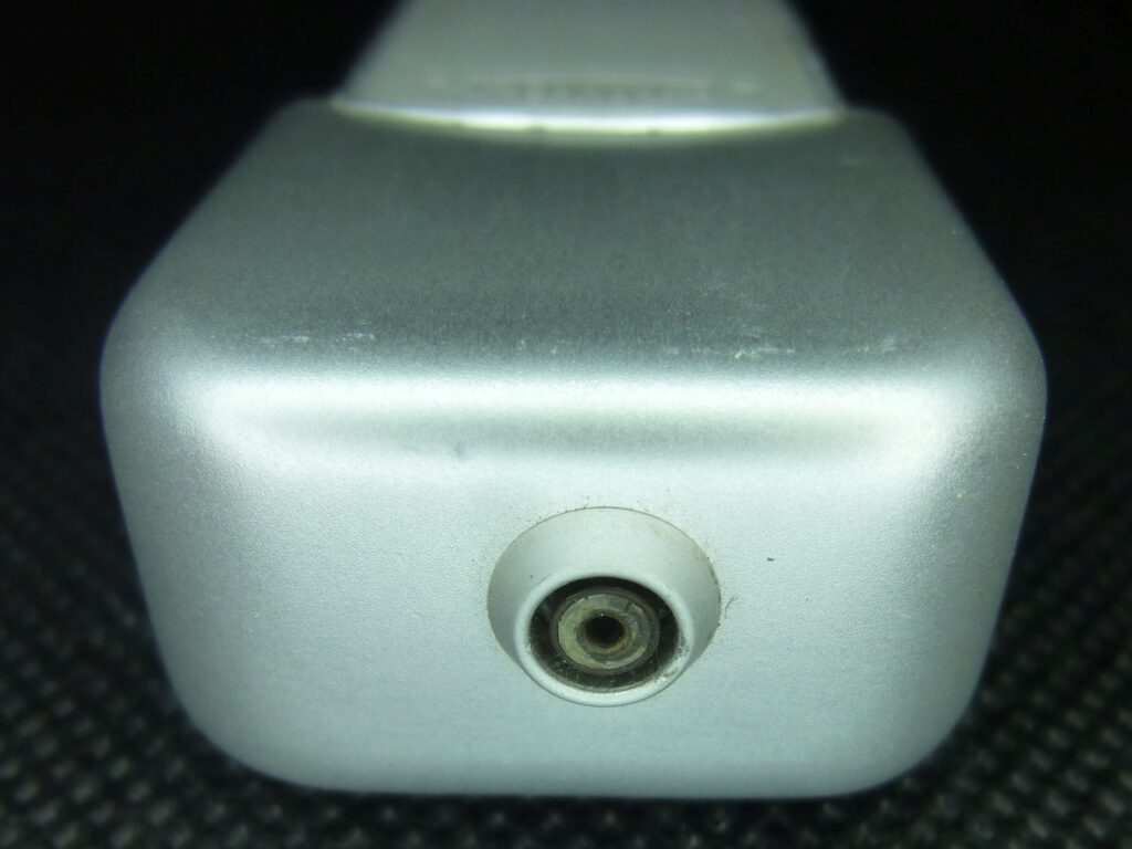
socket for holding the two connectors
The two pictures below show the upper end of an open Minox, i.e. where the flash is attached. The camera shutter has a built-in contact plate which serves as a sync switch that triggers the flash, and this contact is timed to fire the flash at a defined time before the shutter opens.
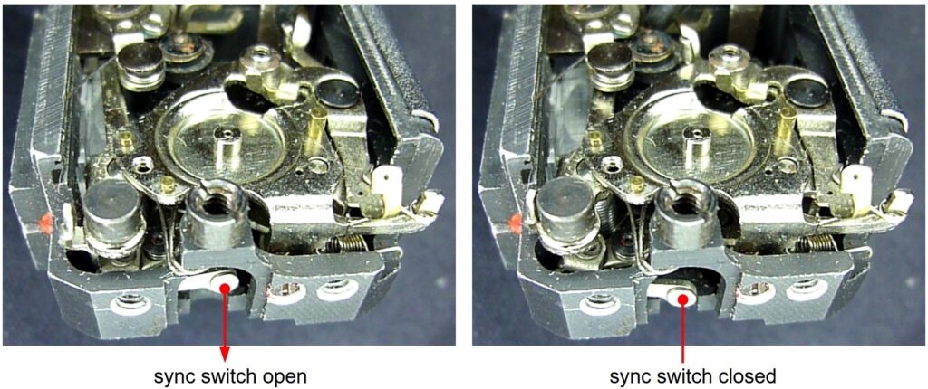
The contact plate is electrically connected to the camera housing. When it is pulled out, it presses against the second conductor of the flash unit and thus closes the circuit from the capacitor to the flash bulb in the flash unit. The flash fires.
On the right we can see how the insulated conductor protrudes from the inside of the camera housing as a pin. The contact plate presses against it to ignite.
This mechanism aligns the time it takes for the flash bulb to reach its full brightness with the time the shutter is open. Watch the switch in action in the following video:
Minox B, escapement partially removed.
In essence, M synchronization is a technology developed to compensate for the delay in flash bulbs and ensure proper exposure in cameras with leaf shutters.
The electrical circuit
In the 1950s, flash units for flashbulbs relied on a relatively simple circuit to generate the current required to ignite the bulb. The core components were a battery, a capacitor, and a trigger mechanism. The electronic circuitry of the Minox AG 1 flash unit followed a common concept at the time. It ensures that a sufficiently strong ignition current is always available, even when the battery is running low. Thanks to Rainer for the explanations in the Blende-und-Zeit-Forum.
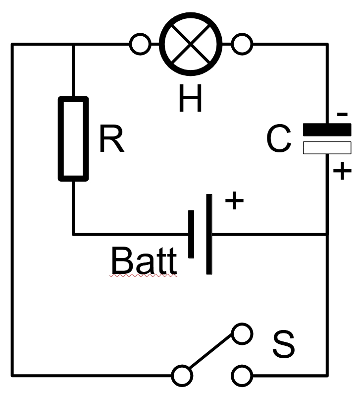
H: AG 1 flash bulb, S: sync contact
As long as the switch S is open, a small current flows from the battery via the resistor R and the flash bulb H to the capacitor C and charges it. The current is so small that the flash bulb is not ignited. As soon as switch S is closed, the maximum current flows from the capacitor to the flash bulb and ignites it.
Battery: The power source was typically a 15 volts high-voltage dry cell battery. This battery provides the initial charge for the capacitor.
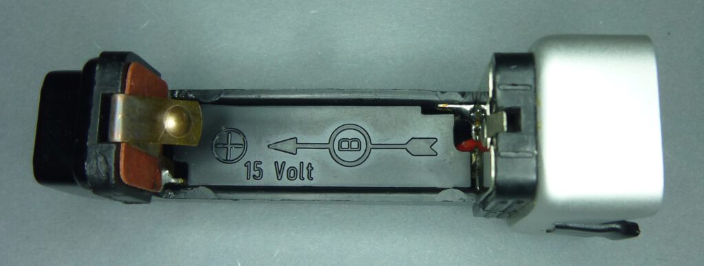
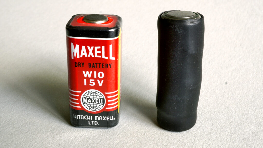
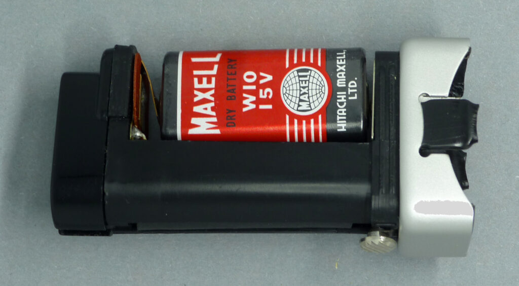
Today, you can easily make a replacement battery yourself using button cells. To do this, take 10 LR54 button cells and a spacer to achieve the required height. The whole thing is stabilized with shrink tube or adhesive tape, see photo above. I made the spacer from an empty button cell, the poles of which I bridged with soldering tin.
The following explanation of the battery in a book on Minox cameras, which was very popular at the time, shows what has also changed in the image of women in the 69 years since this flash unit was introduced:
“The capacitor has a practically unlimited service life, but the battery has to be replaced from time to time. The battery is similar to a woman’s beauty: no one can guarantee how long it will last. The advantage of the battery is that it can be replaced when it gets old and weak. In general, you should buy a new one after two years at the latest.”
Kasemeier, R. (1957): Kleine Minox – Große Bilder, Heering-Verlag, pp. 150-151
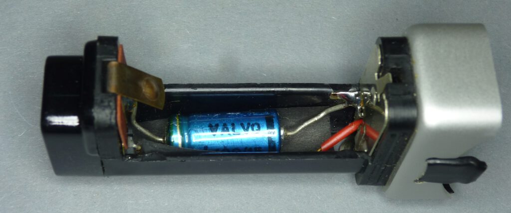
Capacitor: A 100 µF electrolytic capacitor is used to buffer the electrical energy. When the capacitor is fully charged, it holds a significant amount of energy ready to be discharged through the flashbulb.
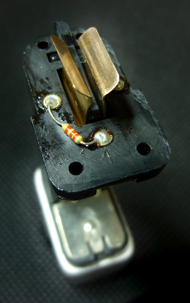
Charging Circuit: The charging circuit consists of the battery, resistor R, flash bulb H and capacitor C connected in series. The 2.2 kΩ resistor limits the current flow to prevent the flash bulb from being ignited by the battery. The current of I = U/R = 15V/2.2 mkΩ = 6.8 mA is not sufficient for this, but charges the capacitor quickly.
As long as an unused flash bulb is inserted, current flows from the battery to the capacitor to charge it. As soon as the capacitor is charged, a very low current continues to flow. This is due to the leakage current of the capacitor. Without a bulb, this circuit is interrupted. The bulb should not be inserted for months to prevent the battery from slowly discharging. After the flash is triggered, the circuit inside the bulb is interrupted. A used bulb can therefore remain in the device without the battery discharging.
Trigger Circuit: The trigger circuit controls the discharge of the capacitor through the flashbulb. It involves the sync contact S, mechanically linked to the camera’s shutter mechanism. When the shutter is released, the switch is closed at the right moment, completing the circuit between the capacitor and the flashbulb.
Flashbulb Ignition: When the switch is closed, the stored energy in the capacitor is rapidly discharged through the flashbulb. This sudden surge of current causes the thin wires inside the bulb to heat up and ignite the combustible material with the pure oxygen inside the bulb, producing a bright flash of light.
Synchronization: To synchronize the flash with the camera’s shutter, the trigger switch was designed to close at the appropriate moment during the shutter’s travel, see above. This ensured that the flash occurred when the shutter was fully open, capturing the image on the film.
Significance for Photography
Before the AG 1 flash unit, the Minox A was limited to daylight or well-lit scenes. This unit significantly broadened its scope – from evening snapshots to indoor photography. Users appreciated the ability to push the boundaries of their Minox A, capturing moments that were previously out of reach. The compact AG 1 bulbs perfectly complemented the camera’s portable ethos. Together, the camera and flash unit could still fit into a pocket – a convenience few systems of the time could match.
A Reflection of Its Time
In 1958, flash technology was evolving. While large bayonet-base bulbs (like the Osram XO) were still common, the AG 1 bulb ushered in a new era: smaller, more efficient, and more portable. It also reflected the transition from battery-powered flashes to capacitor-driven systems. For Minox, the AG 1 underscored their innovative spirit—a company that didn’t just craft cameras but built entire photographic ecosystems.
Today, the AG 1 flash unit is a coveted collector’s item. Its condition varies – many units bear signs of use, but fully functional examples in mint condition are rare and valuable. AG 1 bulbs are still available. For analog photography enthusiasts, it’s a tangible piece of history that brings the era of subminiature cameras to life.
Conclusion
The Minox AG 1 flash unit of 1960 was more than just an accessory – it was key to unlocking the Minox A’s versatility. It embodied the engineering prowess and inventive spirit that define Minox, illuminating new possibilities in photography. Whether for enthusiasts or everyday photographers, the small but powerful device completed the Minox A experience. Holding it today evokes the pulse of an era when technology and creativity went hand in hand – a small but brilliant chapter in photographic history.