There are hardly any instructions on how to open a Minox camera. I had to figure most of it out for myself and would like to share my experiences with you here.
Opening a Minox can be a nightmare if you don’t know exactly what you’re doing. It is easy to irreparably damage sensitive parts such as the shutter blades or make it impossible to assemble the camera. There is also the risk of accidentally changing settings or damaging the complicated internal mechanism.
Page Contents
How to use this guide
These instructions apply to the Minox A, II, III, IIIs, and Minox B, and, with some limitations, to the BL. For the Minox C and LX, only the cap, bottom part, and front cover can be opened in this manner. Opening the other housing parts of these two models is not described here.
The VEF Minox Riga is opened in a completely different way, which is not described here.
In order to service or repair the camera, you have to remove various housing parts. It took me a lot of research, time and Minox cameras to learn how to do it. Since it’s not obvious how to open an 8×11 Minox and there’s a lot you can do wrong, I wrote a comprehensive guide here to make it easier for you.
I have arranged the chapters in the same order as you would proceed when disassembling the camera.
Everywhere, I mention the purpose (Why?) for dismantling the relevant part of the housing. In addition, you will find the housing parts that must be dismantled beforehand so that the current dismantling can be carried out at all.
Please read my Legal Disclaimer before proceeding with how to open Minox camera.
The housing parts of a Minox camera

Remove the cap
Difficulty level
Simple
Risks
Scratching the cover if you slip with the screwdriver.
For what reason?
- Required for the later opening of the control panel.
- You can remove resin from the escapement if you don’t have to remove the control panel anyway.
- However, you must always remove the control panel to oil the escapement bearings.
How?
- Open the film compartment and pull it all the way open.
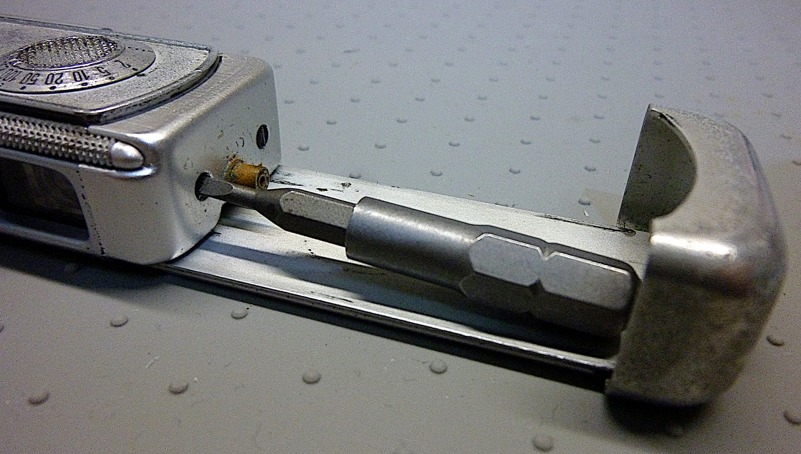
- Loosen the 2 screws on the head side. Since space is limited in length, use a screwdriver bit. A short bit adapter can help apply more torque.
- Remove cap. You can now simply pull back he cap.
Hints
- The screw heads are sealed with a black lacquer that you have to scrape out of the slot with a scriber.
- Since there isn’t enough space for a screwdriver, use a screwdriver bit. If a screw is too tight, you can turn the bit with pliers or use a bit adapter as shown in the photo above.
Remove the bottom part
Difficulty level
Medium
Risks
Overstretching of the blade springs.
Scratching the film chamber when loosening the starhead screw.
For what reason?
• To remove the front cover
• To remove the control panel
• To remove the back
Note: It is not necessary to remove the cap first.
How?
Dismantling
- Be sure to press the trigger first so that the shutter blades are free.
This releases the shutter blades from the locking pins so they can move freely with the lower part in the blade guide. If the shutter is cocked, pulling the lower part would put unnecessary strain on the blade tension springs. - Open the film compartment
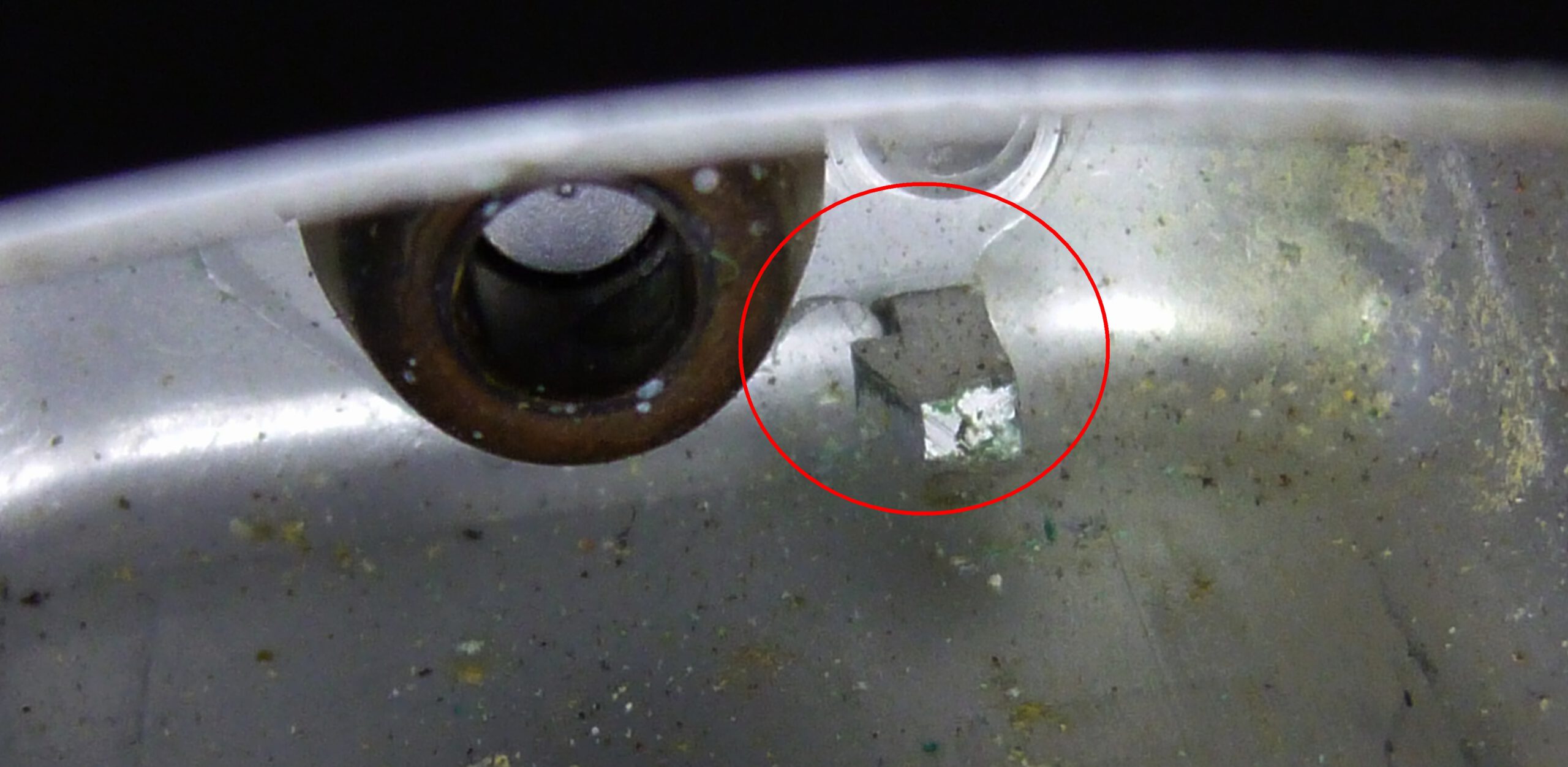
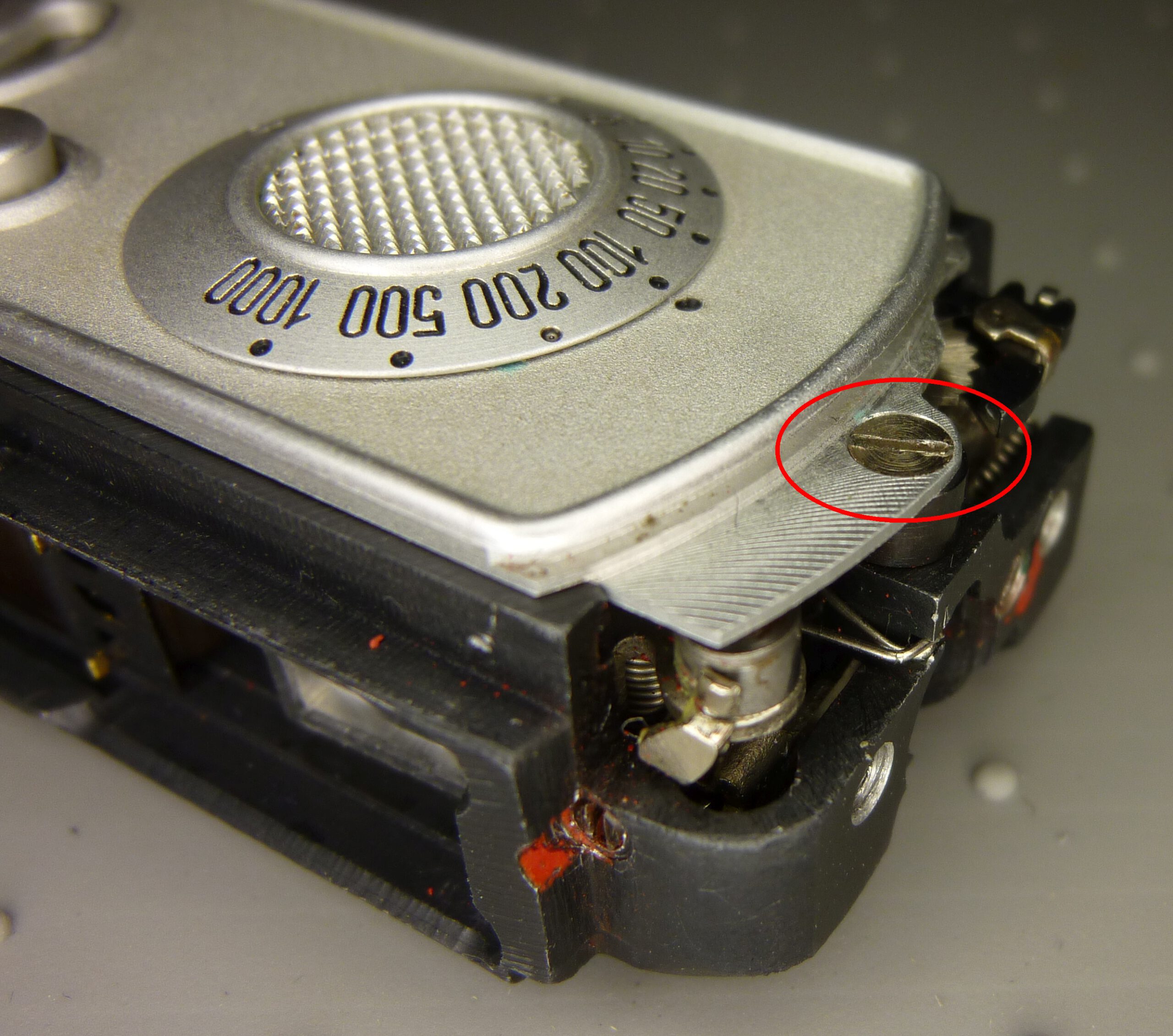
- Unscrew the locking screw above the starhead screw a few turns
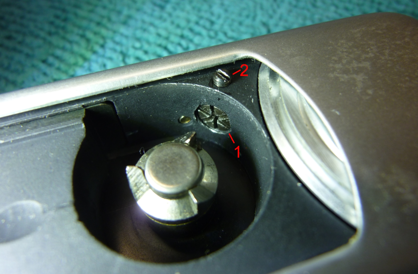
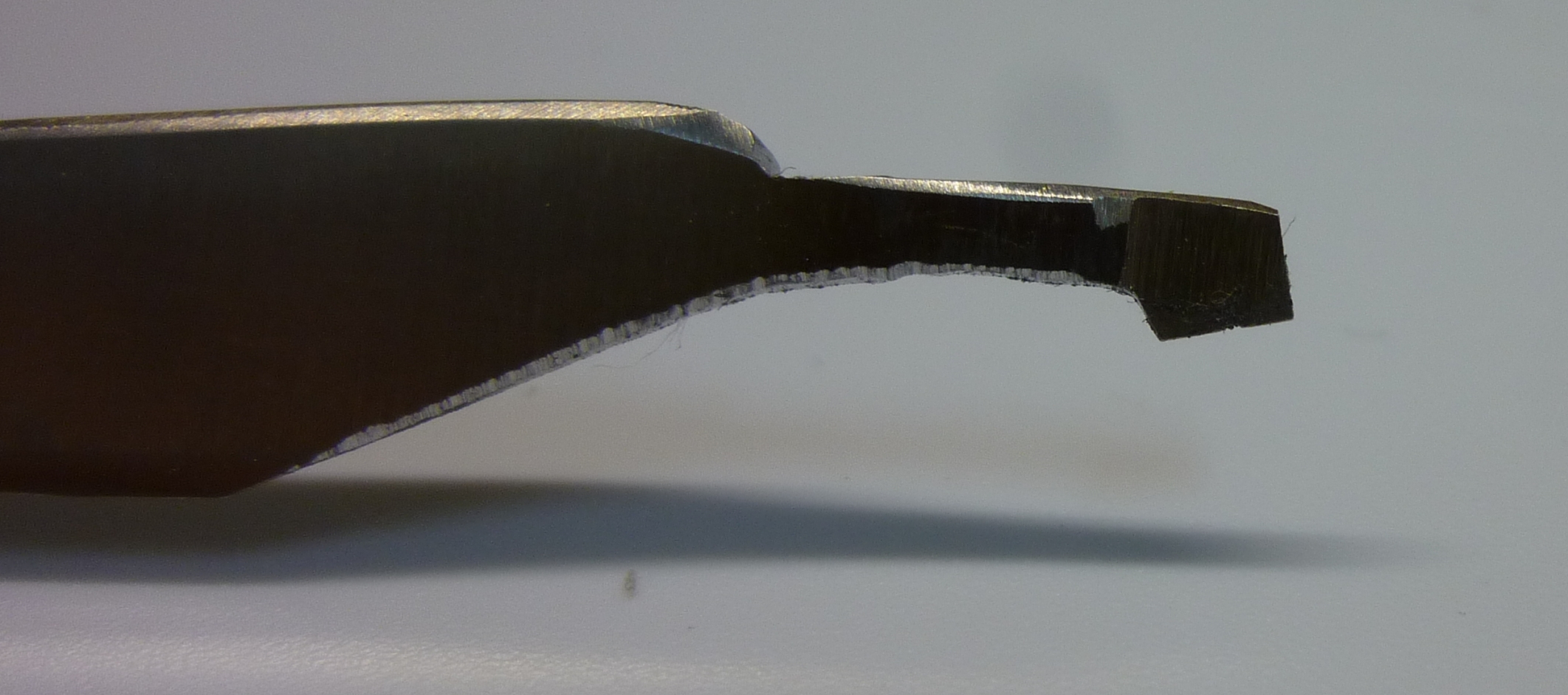
- Turn the starhead screw until it protrudes at least 3 turns. I recommend a special key for this purpose. You can make it from a scalpel by contour grinding. The screw has 3 slots so that you can reach the next slot after turning it 60°. Use the key to turn the screw until you reach the next slot and so on.
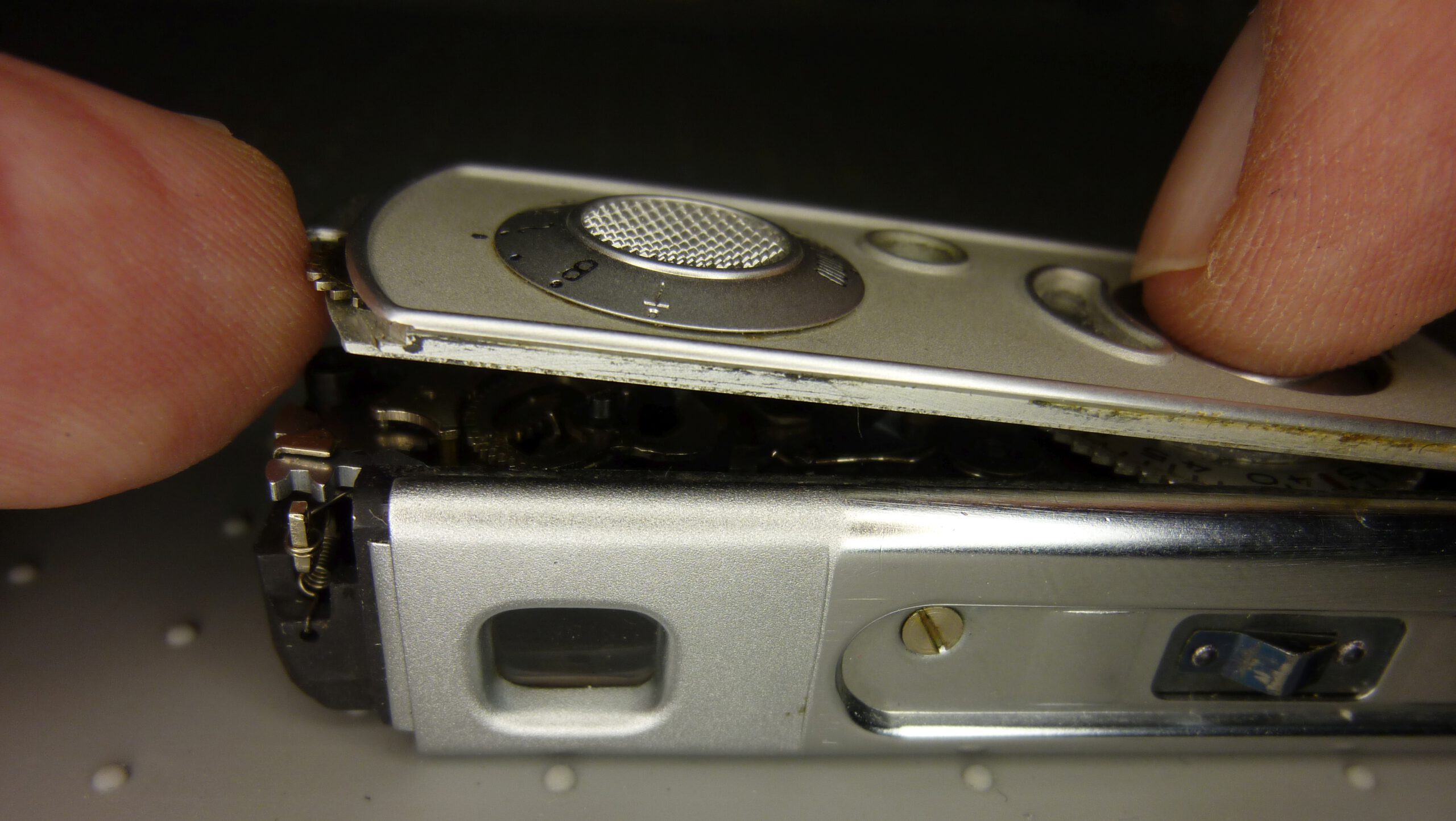
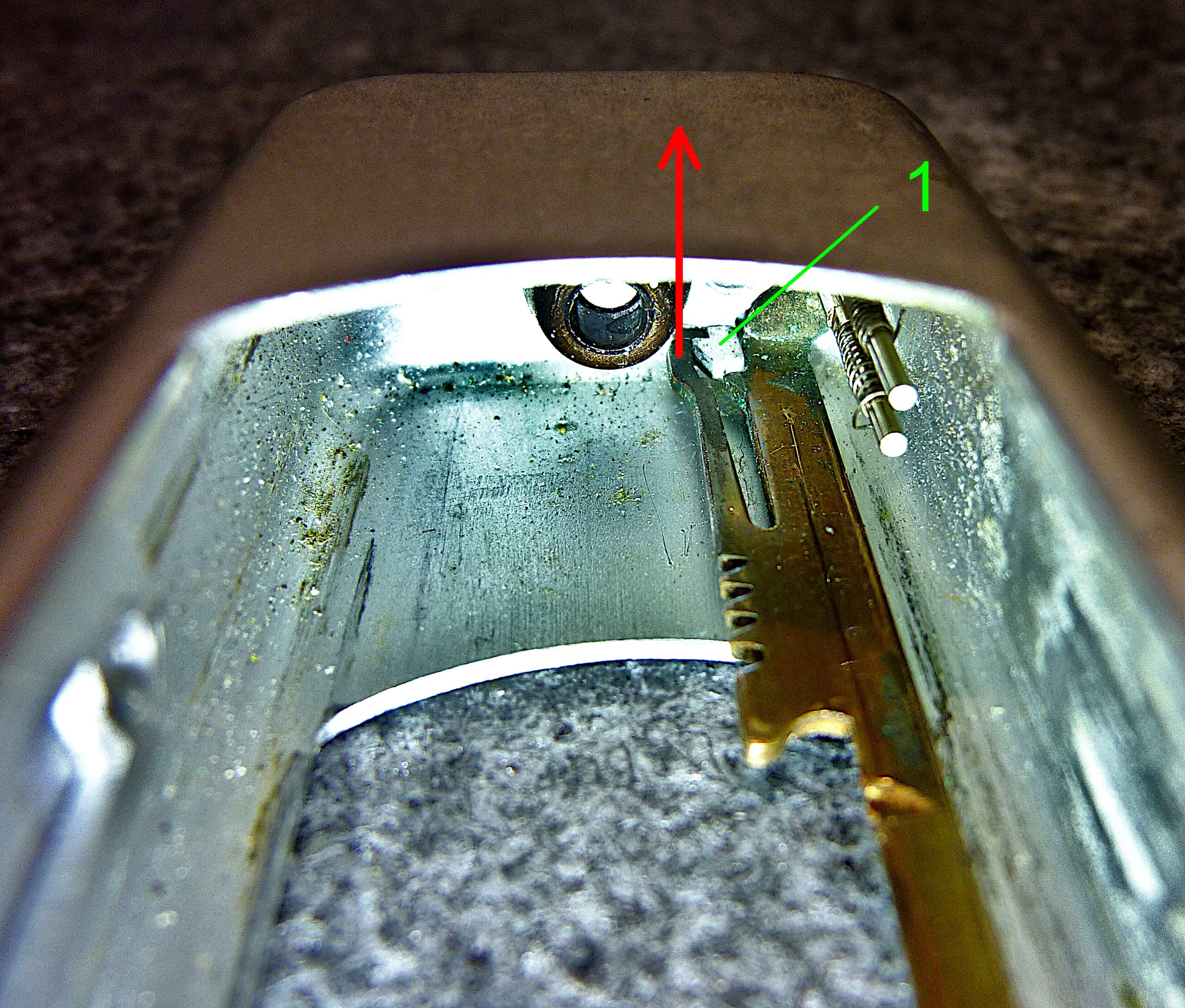
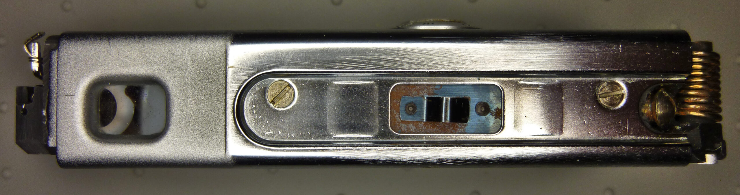
- Turn the camera over and carefully pull off the lower part until the slot between the lower part and the control panel is approximately. 3 to 4 mm large.
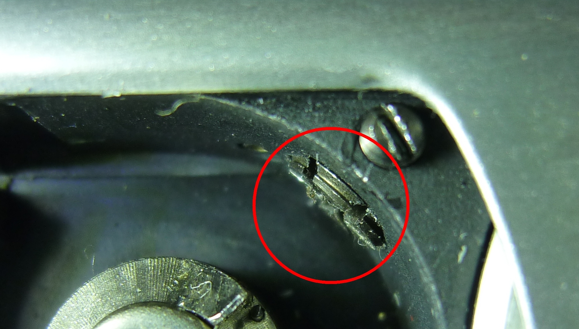
- Insert a thin screwdriver along the spring hooking arm as far as possible towards the lower end of the housing. Then carefully use the tip of the screwdriver to lever the spring hooking arm downwards by approximately 1 mm until you hear a quiet click.
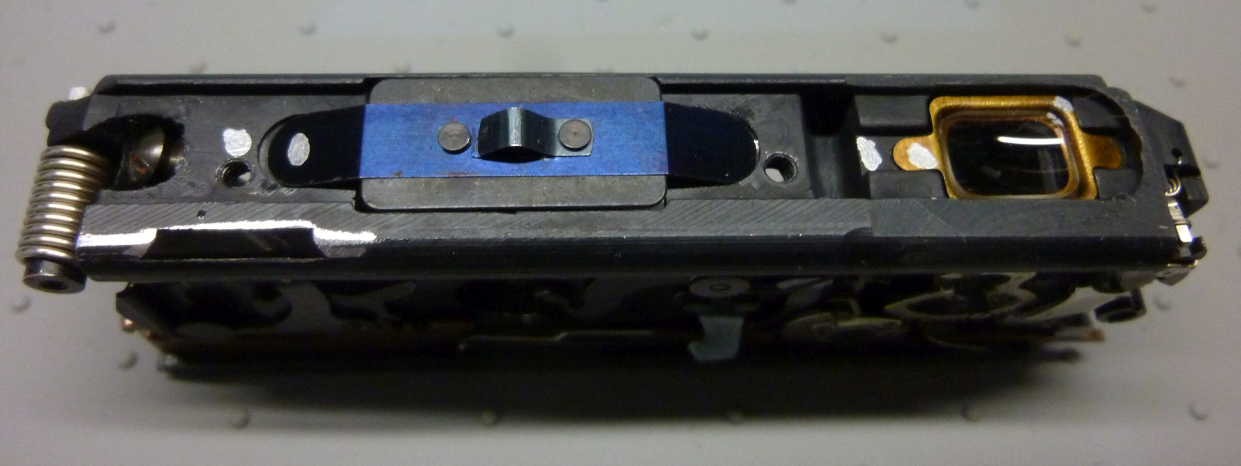
The following two pictures show a look inside the housing for a better understanding.
Now the spring hooking arm is detached from the lower part and you can completely remove the lower part without the spring hooking arm moving.
If the spring hooking arm moves, it is still connected to the lower part. Then stop pulling immediately and first loosen the connection as described above.
Attention: The spring hooking arm can be completely pulled out with the housing’s lower part. However, the highly sensitive shutter blades are then completely removed from their guide. They then hang freely on the spring hooking arm and can easily be damaged. It is therefore better to detach the spring hooking arm from the lower housing part beforehand. However, if the hook cannot be released in the manner described above, there is no other option but to pull out the hook together with the blades and the lower part of the housing completely.
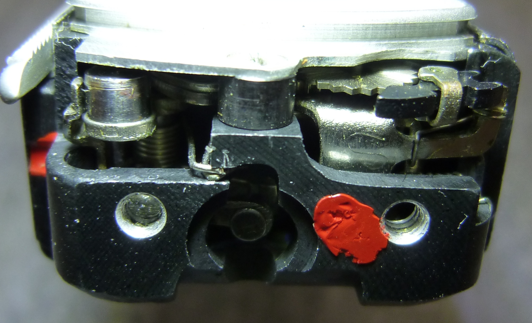
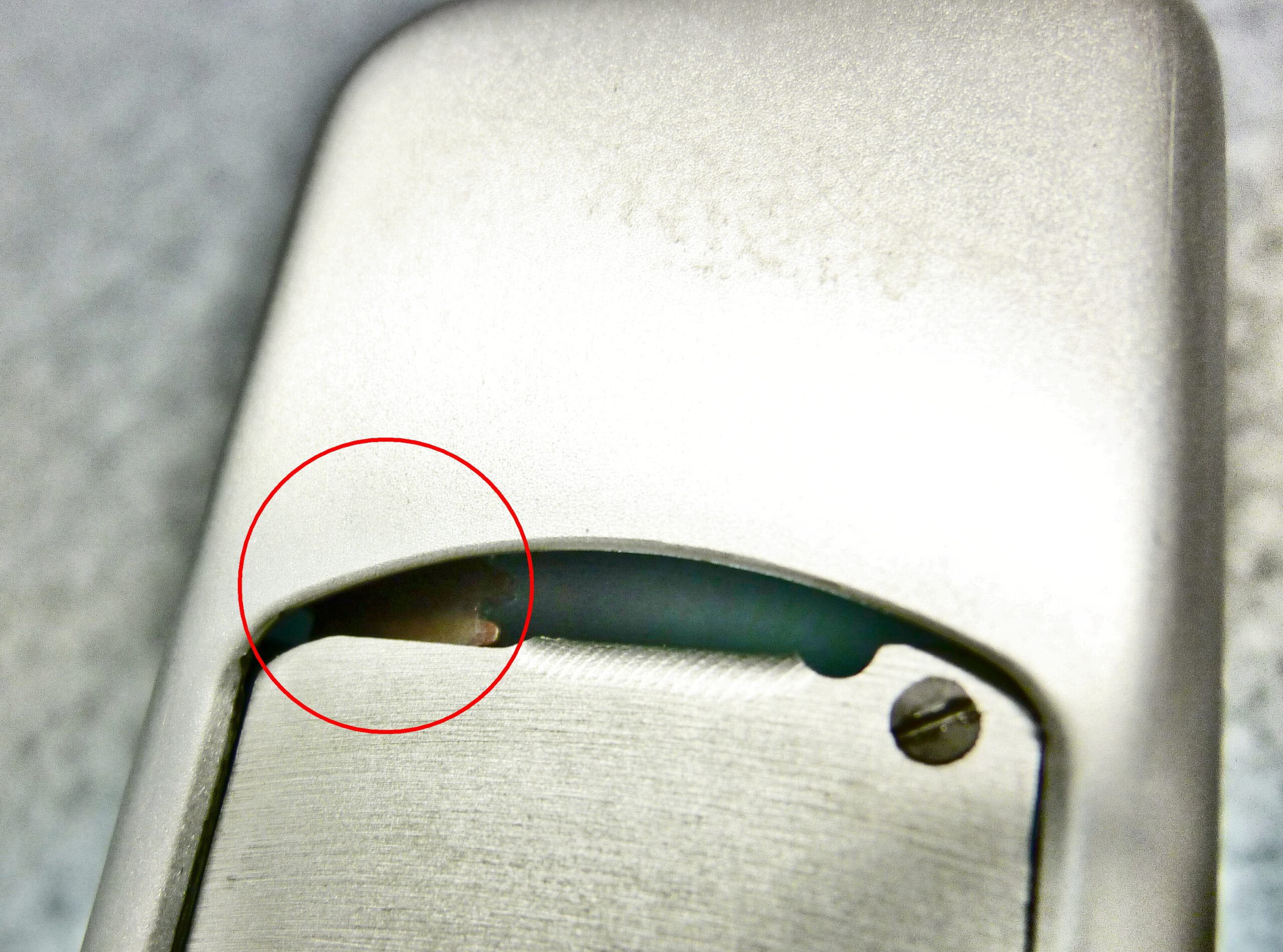
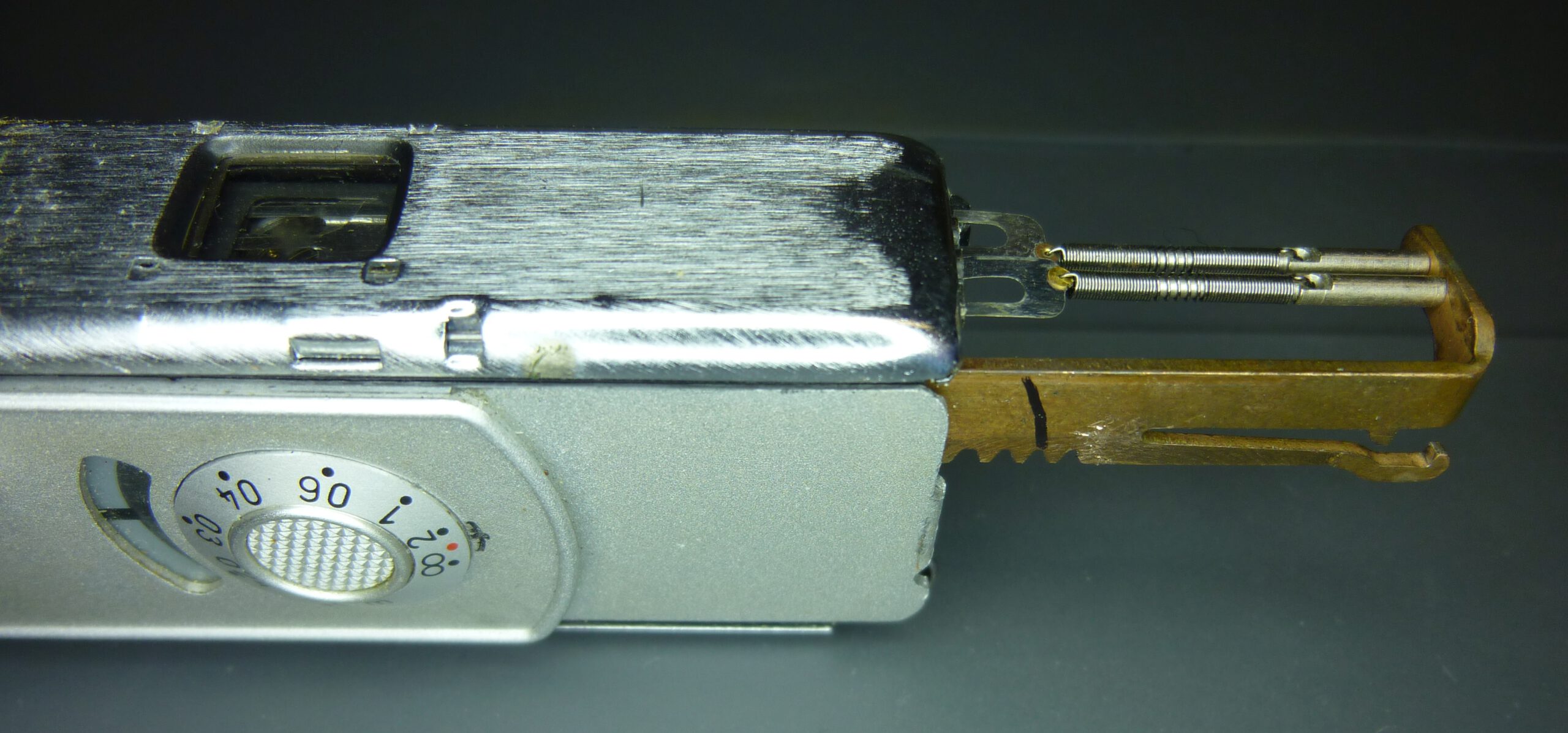
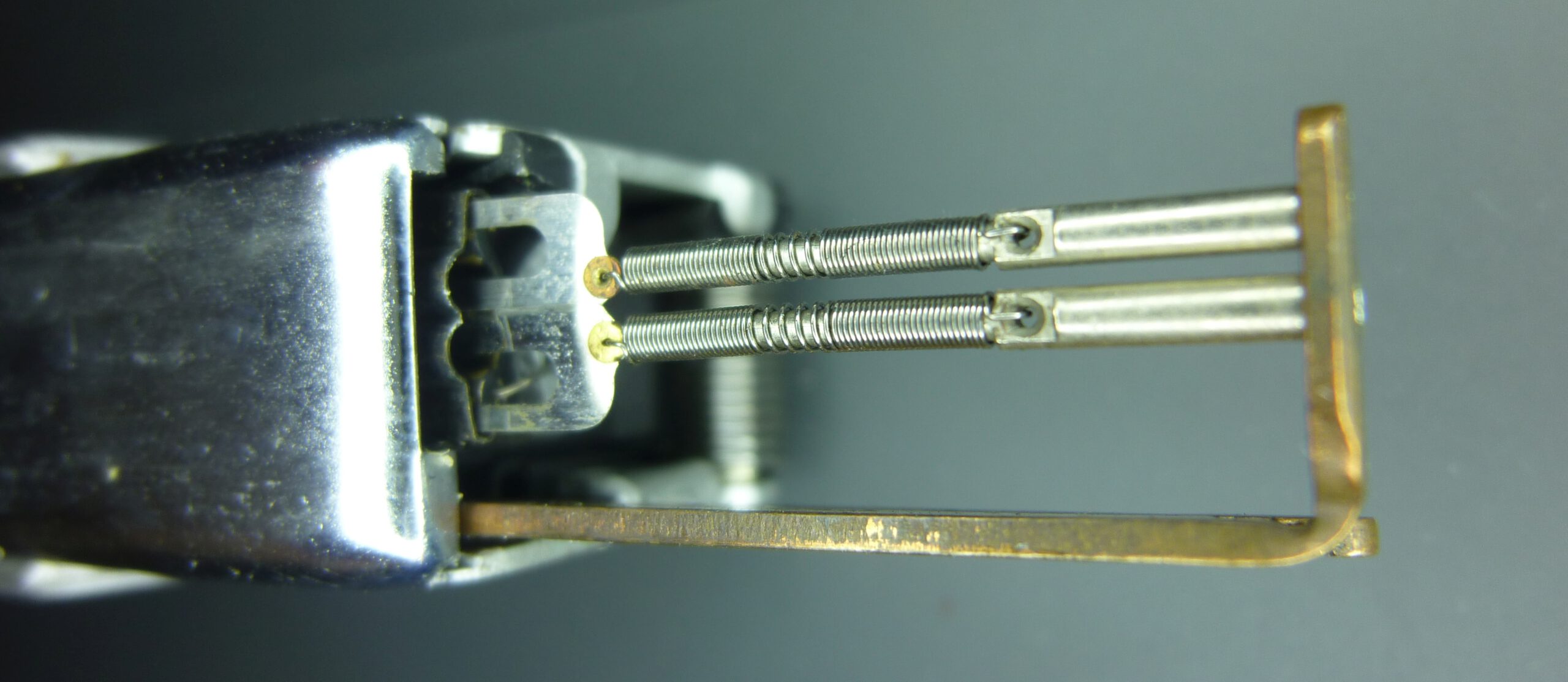
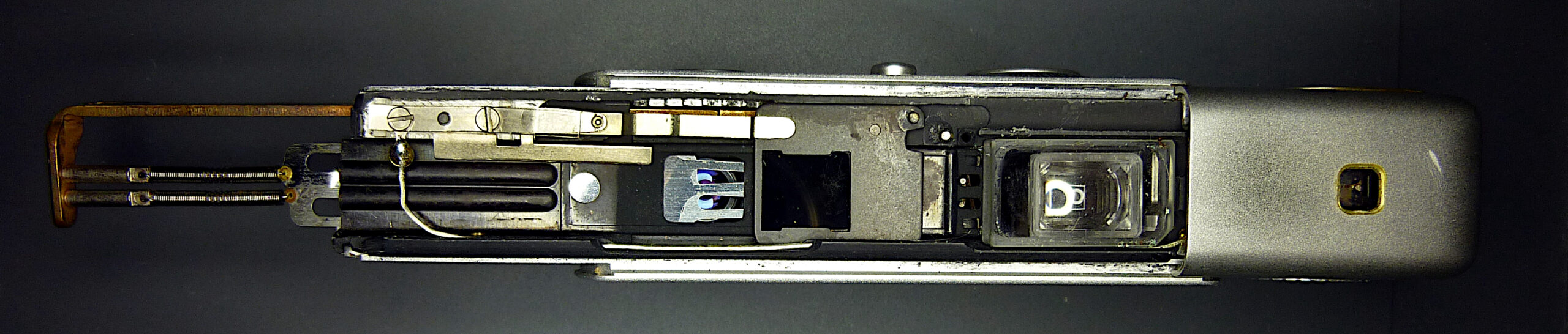
After removing the bottom part, we see the spring hooking arm with the springs and blades protruding from the body of the Minox:
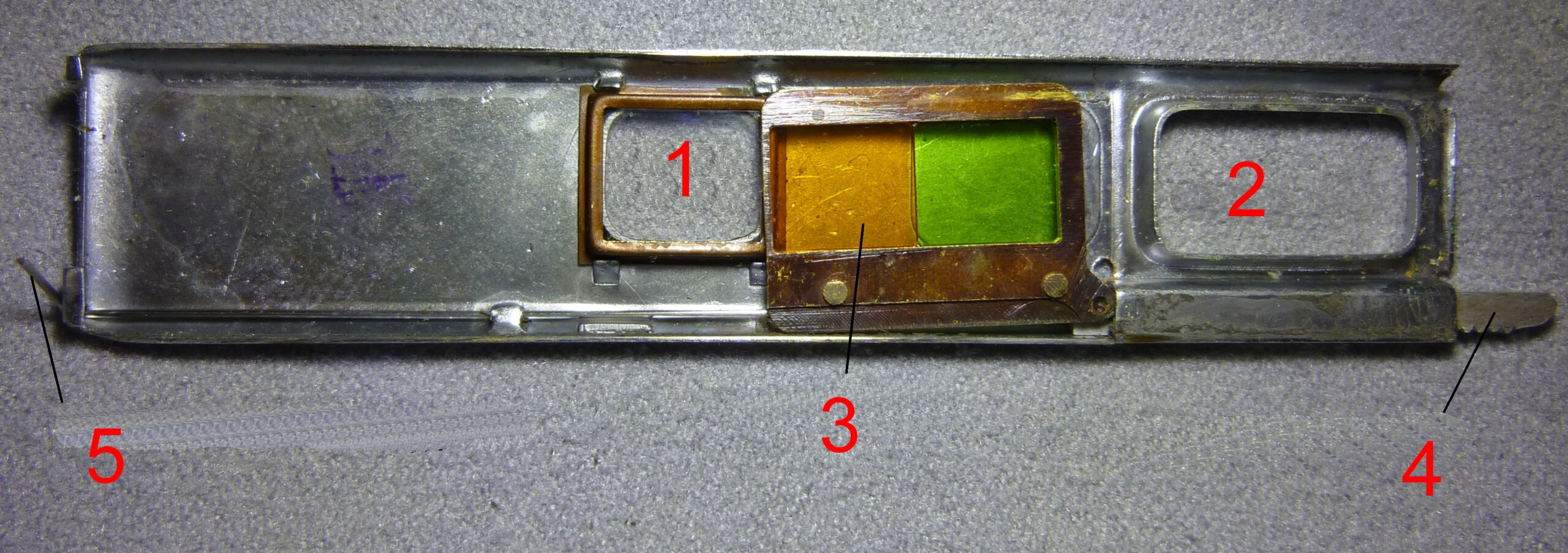
In the picture below left you can clearly see the guides for the blades. On the right the other end of the blades with the recesses for the release pins seen in the lens window:

Reassembly of the bottom part
- Back and front cover must be assembled first.
- At the same time, push in the spring hooking arm and insert the blades into the blade guide. The best way to do this is to clamp the camera vertically in a vice so that you have both hands free.
- Place the lower housing part on the guide rails and push it all the way on so that the spring hooking arm engages in the lower part.
- Screw the starhead screw back in.
Check: The lower part must not be able to be pulled out further than is necessary for tensioning (otherwise screw the starhed screw in further) and it must be easy to move (otherwise loosen the starhead screw slightly) - Tighten the locking screw otherwise the protruding screw will hit the lower part when the camera is pushed together.
Do not forget steps 4 and 5. If the locking screw is not screwed back in completely, the camera will jam when it is pushed together. If you forget to screw the starhead screw back in properly, you will pull the lower part off completely with a jerk during the first cocking of the shutter, damaging both the blades and their tension springs.
Remove front cover
Please read our Legal Disclaimer before proceeding.
Difficulty level
Medium
For what reason?
• To clean the viewfinder
• To clean the filters
• To clean the lens and the lens cover
• To fix problems with defective shutter blades
The front cover is held in place by a screw on the left below the viewfinder. Loosen the screw (with a 1.2 mm screwdriver) and pull the cover downwards.
Note: Be careful not to lose the tiny screw.
The filter unit is loosely attached to the slider under the front cover. The driver ensures that every time the camera is pushed together, the filter is pushed away from the lens.
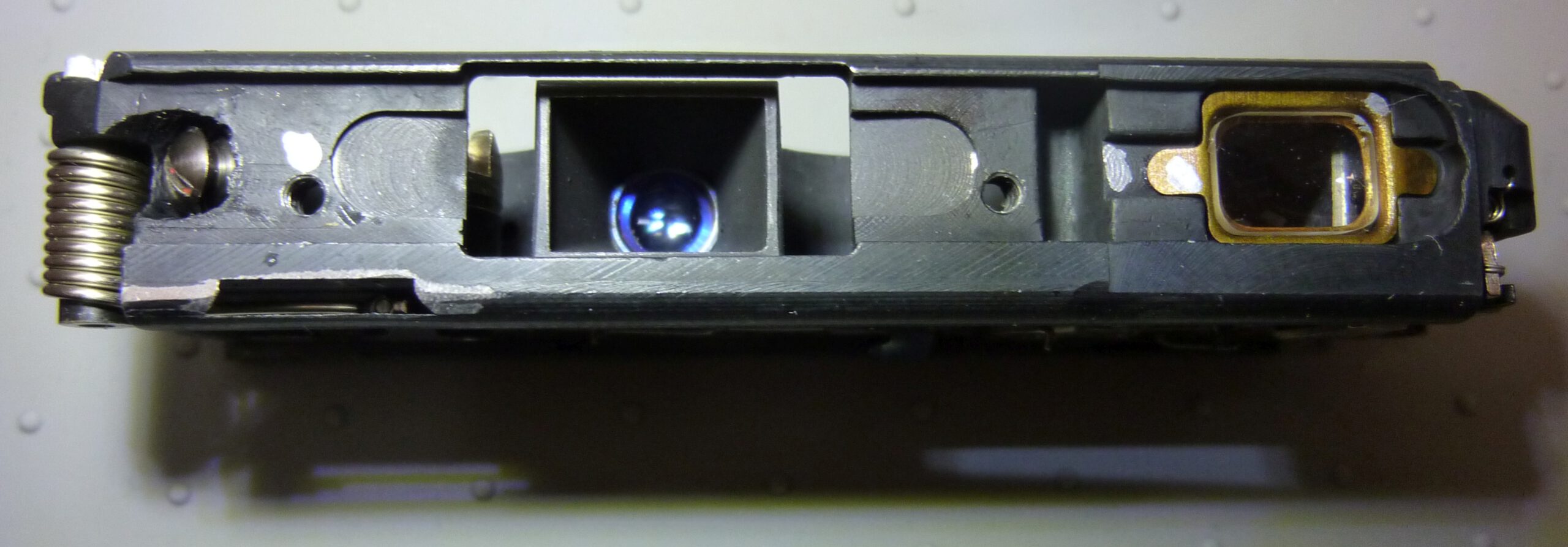
Now you have access to the viewfinder, the filter unit and the blade guide:

Remove the control panel
Difficulty level
Difficult
Risks
The distance dial and image counter disc can fall out, which may require complex readjustment of the lens and the film feeding mechanism.
For what reason?
- Remove resin and oil of the escapement mechanism
- Grease the spring hooking arm
- Grease the guide surfaces on the housing to pull the camera apart
- Set the coupling between distance dial and lens
- Set the image counter
- Set negative distance
How?
Dismantling
- The cap must be removed first.
- Set the shutter speed to ½ s because this time is set automatically when the control panel is removed. Otherwise the shutter speed dial will be positioned incorrectly when it is mounted later.
- Set the distance to infinity as a precaution in case the distance dial falls out.
- Loosen the screw on the upper part of the control panel.
- Now comes the hardest part.
After loosening the screws you are ready to lift the control panel at the top. At the bottom of the control panel there is a tab that reaches into the camera body and secures it from being lifted. Now fix the distance dial with one finger and lift the upper end of the control panel with your other hand. As soon as the control panel is far enough above the distance dial, carefully push the control panel backwards until it slides out of the tab and remove it. The distance dial must be kept in place at all times!
Caution: When the control panel is removed, the distance dial and the image counter disc can slip and fall out of the housing when moving the spring hooking arm. Inserting and adjusting this unit is complex, so always press with one finger when operating the spring hooking arm to cock the shutter.
Reassembly
- Push the spring hooking arm all the way in.
- Position the image counter disk correctly. Check with the control panel in place, see chapter Image Counter.
- Set the shutter speed to ½ s.
- Slide on the control panel at the bottom tab, leaving enough space at the top to avoid touching the distance dial.
- Adjust the distance dial with tweezers until the control panel can slide over it.
- Carefully press the control panel down over the distance dial and adjust both correctly.
- Press the control panel down.
- Screw in both screws
Remove the back cover
Difficulty level
Simple
Risks
- Viewfinder can be spotted
- Pressure plate can be damaged
For what reason?
- Adjust distance setting, set lens to infinity
- Clean the pressure plate
- Clean viewfinder
- Adjust the pressure plate
- Measure shutter speeds with conventional method
Read here my reflective Minox specific method without dismantling the camera
Preconditions
- Bottom part is removed
How?
Dismantling
- Loosen the two screws.
- Remove cover.
- Remove pressure plate.
- Remove the viewfinder glass cover.
Reassembly
Reassembly is done in reverse order.
Summary on how to open a Minox camera
Knowing how to open a Minox camera is a prerequisite for being able to carry out repairs. I hope this has been described in sufficient detail here. You can now start to repair your Minox.
Nevertheless, something may be missing or unclear. In this case, please use the comment function at the end of the article.
Excellent page but could you add Removing the bottom and cover from a Riga. This appears to be a iii. Your site is an amazing Minox resource
Thank you for your positive feedback!
I took your comment as an opportunity to include references to the models I describe in the “How to use this guide” section.
The Minox Riga is constructed quite differently from its successor models, both in terms of its housing and its internal components. It is much more difficult to open. Above all, the individual parts of the Riga are not readily interchangeable because manufacturing tolerances were not as precise back then. As a result, every Minox Riga is virtually one-of-a-kind. A general description is therefore not possible. I ask for your understanding.