The shutter blades are the final link in the process chain of the exposure system. They must ensure that the lens is fully open during the exposure time and otherwise closed so that no light reaches the film.
Integration in the Minox exposure system
The shutter blade mechanism is the fifth subsystem of the Minox exposure system.
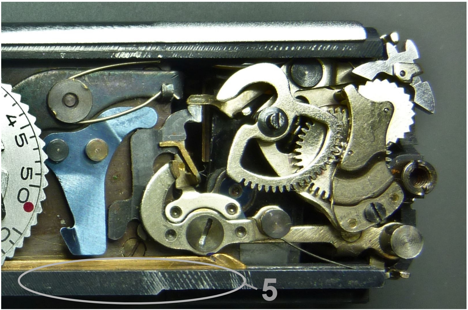
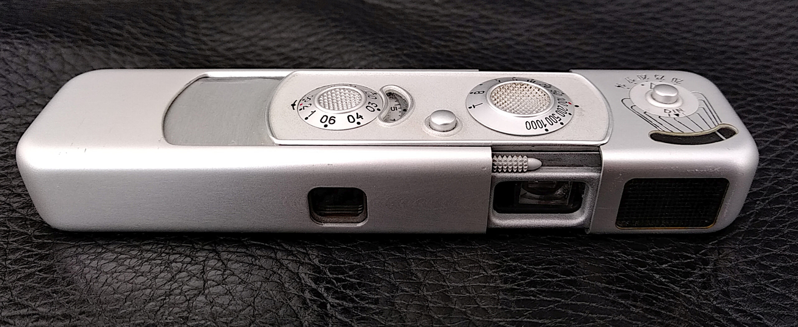
While we have been looking at the Minox from above, we will now change our perspective and look at the front of the camera:
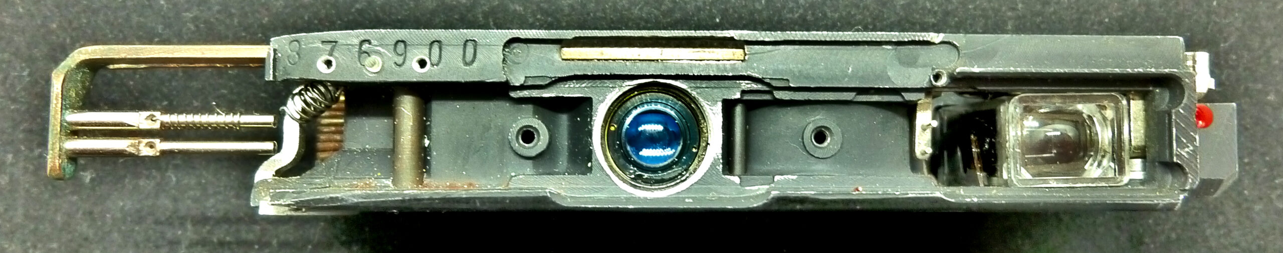
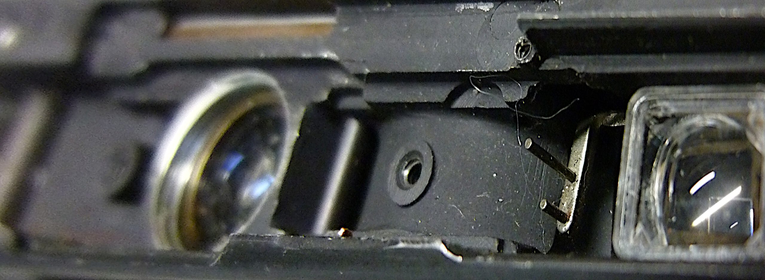
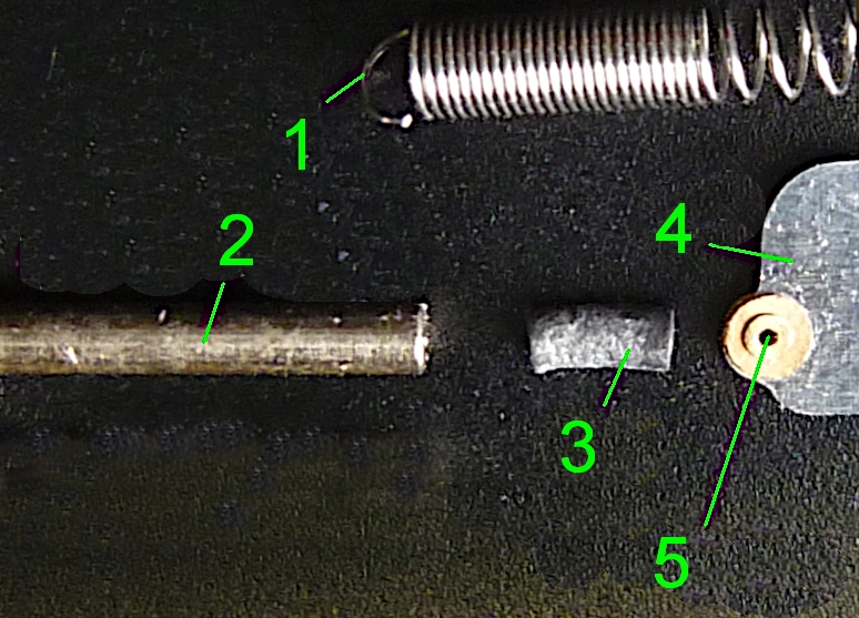
If we remove front plate and lightmeter, we see the parts of the shutter blade mechanism:
From right to left we see:
the viewfinder,
the two pins of the locking blade arm 4b in the eyelets of the blades,
the brass blade guide,
the closing blade in the circular window,
the opening blade in the rectangular window in front of the lens,
the guide channels of the two blade tension springs,
the tension springs,
the spring hooking arm.
Overview
The Minox has a unique guillotine shutter, which consists of two stainless steel blades, each of which is firmly connected to spring hooking arm via a tension spring. On the other side of the blades there are eyelets into which two pins connected to the arm of the blade locking arm.
Before we go into the details check out the excellent animation of the Minox shutter blades by Tristan da Cunha:
Also note the two green pins on the right. They are crucial for controlling the selected exposure times. The same in reality:
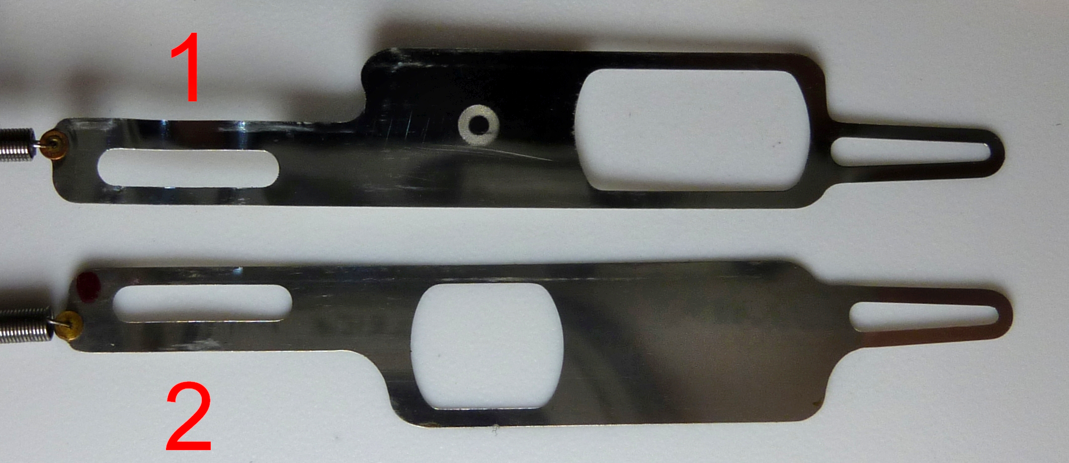
The shutter blades
The two blades lie one above the other in front of the lens. The opening blade (1) lies next to the lense, the closing blade lies above. They are made of 0.4 mm thick stainless steel and weigh just 0.08 g (own measurements).
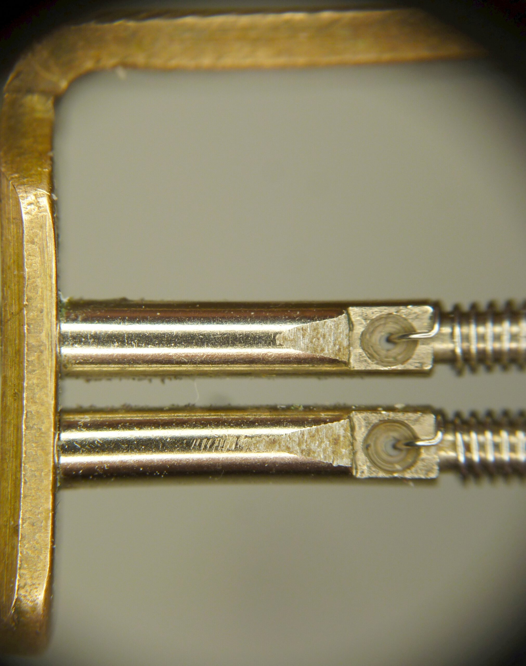
The camera’s blade control mechanism operates den blade locking arm 4b, at the end of which there are two pins that lock the blades, see the two green pins on the first video. The next picture shows the lever with the two pins fixed on it. Note that the two pins of different lengths are attached to the same arm. So they can only be moved together. As we’ll see later, this is a brilliant idea.
By swinging the blade locking arm up or down, the two pins are moved up or down. In the upper position they hold the blades against the spring force, in the lower position they release them. The speed of the panning movement is determined by the escapement. Watch again the video animtion above and have a look at the pins!
In the next image we see the same, but with shutter blades. You can clearly see how the pins hold the shutter blades in place. The top sheet of the blade guide has been removed so that you can see the blades better.
The spring hooking arm connected to the tension springs is firmly hooked to the lower part of the housing, which releases the lens and viewfinder when the camera is pulled apart, thereby putting tension on the tension springs of the blades.
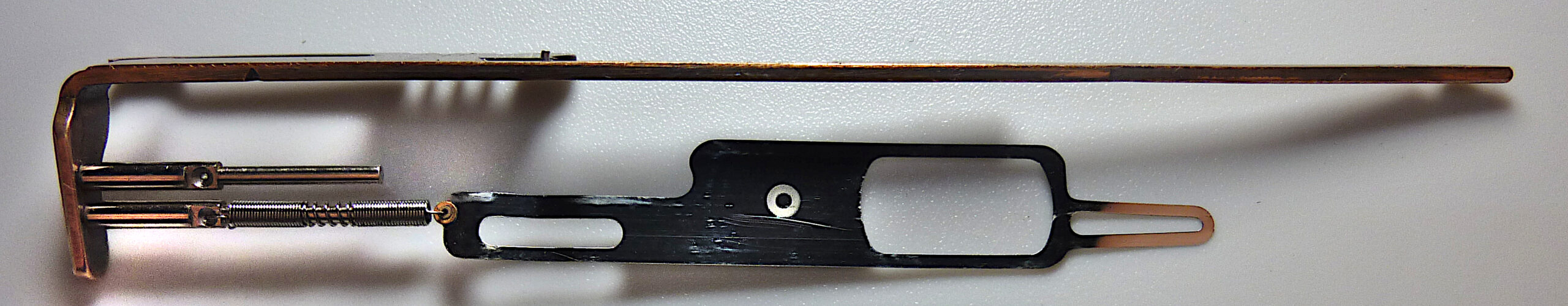
The two tension springs each exert a spring force of approx. 1.6 N (own measurement) on the blades. This means that they are pulled into the end position when triggered.
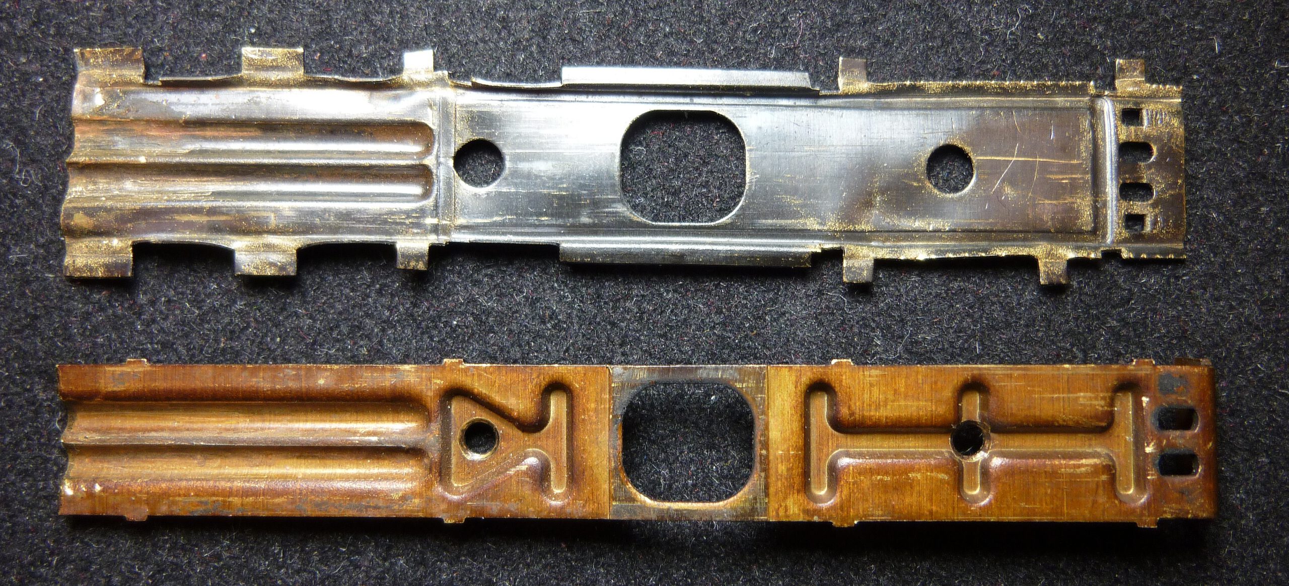
The springs and blades run in a guide plate made of a brass alloy. The stainless steel – brass sliding pairing and the loose guide ensure very low friction without any lubricants. The guide consists of two parts that are connected with tabs. The channels for the tension springs are clearly visible on the left.
The trigger cycle
The following description concentrates on the process with a focus on the shutter blades. For a complete overview of the Minox exposure system, see here.
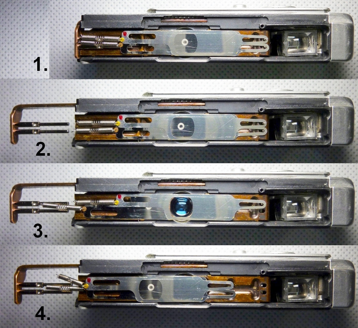
The trigger cycle takes place in four steps, see photos below:
- The camera is pushed together. With that
a) the blades are pushed all the way towards the viewfinder
b) the shutter is cocked, the springs are wound up and
c) as soon as the eyelets of the blades have reached the locking pins, the pins are swiveled upwards.
The window of the closing blade is now directly above the lens and that of the opening blade is to the right of the lens. Now the lens is covered only by the opening blade.
Note that both locking pins are mounted on the same lever. The different heights of the pins are crucial. - The camera is pulled apart. By this
– the front of the camera is opened and
– the tension springs of the blades are tensioned.
The circle on the bottom blade tells the user that the camera is ready to shoot. - The shutter button is pressed and
– the blade locking arm immediately swings down far enough for the short pin 1 to slip out of the eyelet of the opening blade 1, releasing it. The blade locking arm is then blocked by the escapement.
– Now the windows of both blades are on top of each other in front of the lens and thus expose the lens. The exposure begins.
– At this moment the escapement begins to run and blocks the movement of the lever according to the selected exposure time. This means that pin 2 initially remains in its eyelet and holds the closing blade in place. - After the shutter time has elapsed, the escapement releases the blade locking arm again and it swings further. This causes the long pin to slip out of the closing blade, releasing it. Through this
– the window of the closing blade slides from to the left, whereby
– the lens is closed, although the window of the opening blade remains in front of the lens.
Characteristics of the Minox shutter
In contrast to focal plane shutters the Minox the shutter window opens completely even at the shortest shutter speed of 1/1000 s. The kinematics of the shutter ensure that the closing blade only begins to close after the opening blade is in its end position.
The well-known image distortions (see Lartigue’s famous photo Le Grand Prix A.C.F.) caused by focal plane shutters at shortest shutter speeds are thus avoided. This is only possible because of the very small mass of the blades, which can therefore be accelerated extremely quickly. This is one reason why the Minox can cover the range from ½ to 1/1000 s with just one escapement.
The shutter speed for 1/1000 s is therefore determined by the difference in length between the two pins in conjunction with the maximum speed at which they can move downward. For all other shutter speeds, the escapement delays the blade locking arm in accordance with the preset shutter speed.
The physical behavior of the Minox shutter
Movement of the locking pins
The length of the two locking pins differs by 1.7 mm. The pins must therefore cover this path within the selected shutter speed. The exact process and speeds are explained here.
At a selected shutter speed of 1/1000 s the pins run at 1.7 m/s ( ≈ 6 km/h = 3.7 mph), see here for the calculation. These are low speeds that can be easily controlled.
Movement of the blades, physical considerations
The speed of the blades themselves is also limited. The blade covers a total distance of 8mm on its path. A spring force of approx. 1.6 N acts on the blade’s mass of 0.008 g.
With an acceleration a, a body covers the distance s during t seconds
s = ½ * a * t2
With a spring force of 1.6 N and the blade’s mass of 0.008 g the accelaration becomes :
a = F / m = 1.6 N / 0.00008 kg = 20000 m/s2
From this and a distance s of 8 mm the time t is calculated to be
t = √(2 s / a) = √( 2 * 0.008 m / 200000 m/s2) = 0,0009 s ≈ 1/1000 s
This means that the blade needs approximately 1/1000 s for it’s path, which corresponds to an average speed of 8 m/s (≈ 30 km/h, calculated without friction).
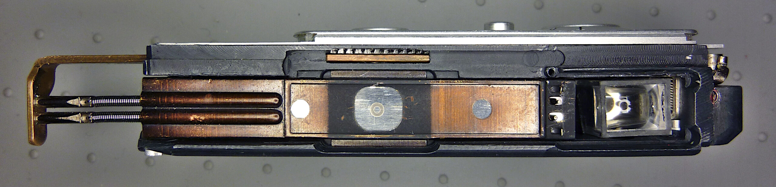
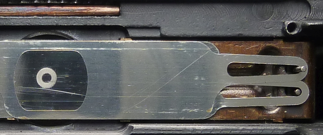
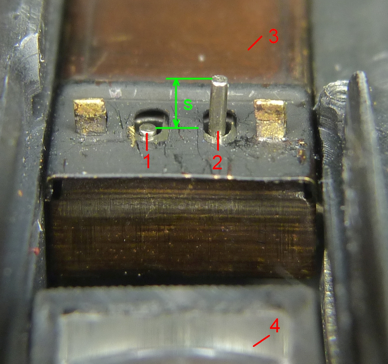
This explains why the Minox shutter does not behave like a focal-plane shutter even at a shutter speed of 1/1000 s. After pressing the shutter release button, escapement lever 4a and blade locking arm 4b are accelerated to their maximum by the associated torsion springs and run to the end stop. To ensure that exposure begins immediately, the opening blade has a wider window that extends to the edge of the lens:
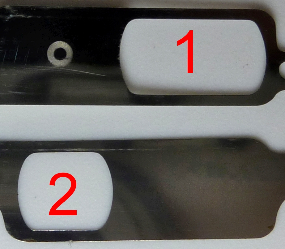
2: Window of the closing blade
The lens is under the gray circle. You can see that the window (1) extends directly to the lens. This means that the exposure begins immediately after the opening blade starts to moveto the left.
After 1/1000 s, the closing blade is also released and starts running. At exactly this moment, the opening blade has already reached the stop and the entire lens is open for this moment. After another 1/1000 s, the closing blade is at the stop and the lens is closed again.
The blade hits the blade stop with a speed of 18 m/s ≈ 65 km/h. For comparison: A Formula 1 car needs a full 2 seconds from 0 to 65 km/h instead of 1/1000 s, see also Minox C advertisement July 1970: “Acceleration inside is over 3000 times faster than a starting racing car. In fact, the blades of the shutter system are so fast that you can accelerate from 0 to 50 km/h in 1/2000 of a second.)
In order to cushion the impact of the blade on the stop, a rubber buffer is installed between the spring hooking arm and the blade within the tension spring. The buffer has a cylindrical shape with 0.9 mm diameter and 2 mm length (own measurement).
Movement of the blades, experimental considerations
To show the actual conditions I carried out an optical measurement of the shutter opening (ShutterSpeed app / PhotoPlug using the reflex method).
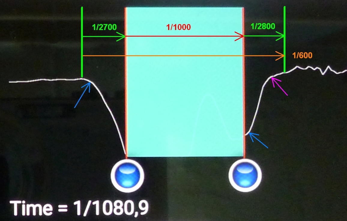
Mint-colored area: shutter fully open, the width corresponds to approximately 1/1000 s.
In the experiment, the blades are illuminated from outside with a lamp. The reflected light is measured and recorded. Since the blades reflect strongly, high brightness values are measured when the lens is closed. When the lens is open, however, little light is reflected. The brightness progression is displayed graphically. The time during which the lens was fully open was measured in the graph (mint-colored area). The time scale can be derived from this.
The blades open and close within 1/2700 or 1/2800 s. In between there is 1/1000 s when the lens is fully opened. The acceleration phases of the two blades are clearly visible (blue arrows). The entire process takes 1/600 s. For the effective exposure time, the average of the opening and closing times must be added to the time in which the shutter is fully open. This results in an exposure time of approx. 1/(1/2750 +1/1000) = 1/730 s.
The deceleration of the closing blade can be seen in the purple arrow in the picture above. With the opening blade, the deceleration cannot be seen, as this happens when the shutter is fully opened. Therefore, the amount of light does not change when the opening blade is delayed.
Conclusion
We have seen that the Minox shutter is not a focal plane shutter with its well-known problems, but a highly developed guillotine shutter that can easily handle 1/1000 s thanks to its extremely small mass and high acceleration forces.
This is also possible because the Minox exposure system as a whole has been divided into modular subsystems, each of which could be optimized individually. The energy stored in the springs was distributed in such a way that every movement could be performed optimally. In the Minox shutter five independent springs are used to
– adjust the escapement,
– swivel the escapement lever,
– swivel blade locking arm with the locking pins,
– drive the opening blade and
– drive the closing blade.
This means that each spring can be optimized precisely for its intended purpose and unwanted mutual influence is ruled out. An ingenious construction!
Back to the article The minox exposure system
References
Oleson, Rick: How it works – The Minox Shutter
The Camera Craftsman, Vol 23 No 6 1977: The Minox B