
The Minox film feeding mechanism
Minox film has no perforations. Therefore, a much more complicated design had to be devised for the Minox film feeding than with other cameras.
If you already know that you are experiencing issues with film transport, take a look here to find out how to resolve them. Otherwise, the following text explains how the Minox film feeding mechanism works and why problems can arise.
In cameras with perforated film, a sprocket ensures that the same length of film is always transported after each shot. After each shot, the sprocket rotates and moves the film through the perforation by the required length. To get equal distances between the negatives, the sprocket simply has to be rotated by the same amount each time.
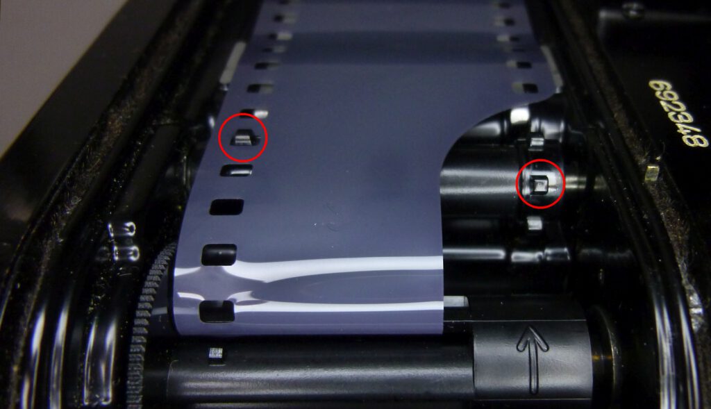
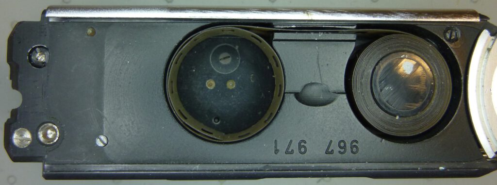
The 8×11 Minox uses unperforated film. On one hand this has the big advantage that you can make Minox films yourself from standard 35 mm film. However, the lack of perforation requires a special design for film transport. In the following picture we can see the situation in a Minox with a half-exposed film (the cartridge has been left out so that the film can be seen).
Left: supply chamber, right: take up spool
The challenge
With the Minox the take up spool is rotated after each photo. The spool pulls the film out of the supply chamber until an unexposed piece of film is again in front of the lens. Now, with each rotation of the spool, its diameter increases according to the film being wound, so that an increasingly longer piece of film is rolled up per revolution. This would result in the distances between the exposed photos on the film becoming ever larger. This wouldn’t harm the image quality but it would waste film.
In fact, Minox cameras use a special patented mechanism to expose unperforated films with correct distances between frames over the entire length of the film:
Other subminiature cameras that work without film perforations, such as the Mamiya Super 16 or Edixa 16, do not have such a mechanism. They accept that there are increasingly large distances between the images and thus film is wasted.
The Minox patent
The Minox has a patented mechanism that ensures to feed the film by steps of equal length, in spite of the increase of diameter of the film roll wound on the spool. For this purpose, the information from the frame counter is used by controlling the advance of the film depending on the number of photos already taken. All of this is done purely mechanically.
left: camera pulled apart, right: camera pushed together
To make the following description easier to understand, please watch the video below.
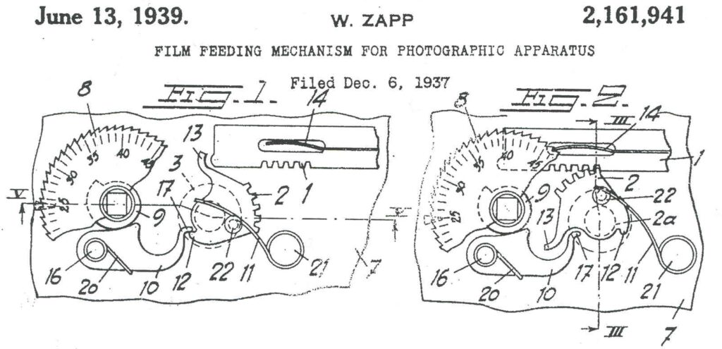
The above drawing shows that a helical cam 9 is attached below the image counting disk 8. This cam has a diameter that increases with the number of images and reaches its maximum at image 50. A lever 10 is engaged to this cam. At the other end, the lever has a nose that engages with a cam 12.
To transport the film, rack 1 is moved to the left by pushing the camera together. The front end of the rack hits nose 13 and begins to rotate the film spool 2a. Afterwards, teeth 2 also come into engagement with the rack and ensure further rotation. Before the film feeding process, the helical cam 9 determines when the rotation of the film spool 2a begins and how many teeth 2 are moved by rack 1. As a result, the angle at which the film spool 2a is rotated decreases with each photo taken, so the distances between the negatives remain constant.
The thickness of the film, the shapes of the cams 9 and 12 and the shape of the lever 10 are working together to exactly match this. Part 2a, the axis of the film spool is therefore the most important part of this mechanism. In reality, the mechanism looks like this:
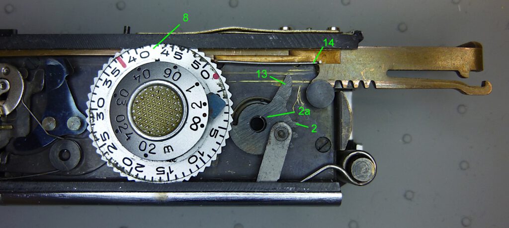
At the end of the feeding process the spring wire 14 (fastened to the rack) turns the image counting disc by one number. With it turns the helical cam 9 which moves lever 10 in the next position.
Minox film feeding videos
The following video shows the film feeding mechanism in action. Note how at the end of the process the spring wire 14 turns the image counting disc by one number:
The same seen from the back of the camera, the following video shows an original 36 exp. Minox film being wound onto the spool. The film cartridge was removed to view spool and film:
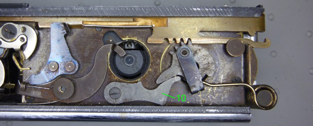
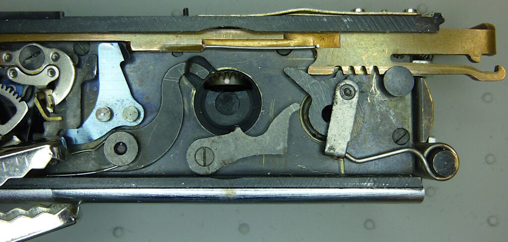
With the image counting disk and the distance dial removed, you can see lever 10:
On the underside of the image counting disk you can see the cam 9 that controls lever 10. Note the transition of the cam from the largest (photo no. 50) to the smallest (photo no. 1) diameter. This difference of the diameters is only 1 mm.

Minox film advance examples
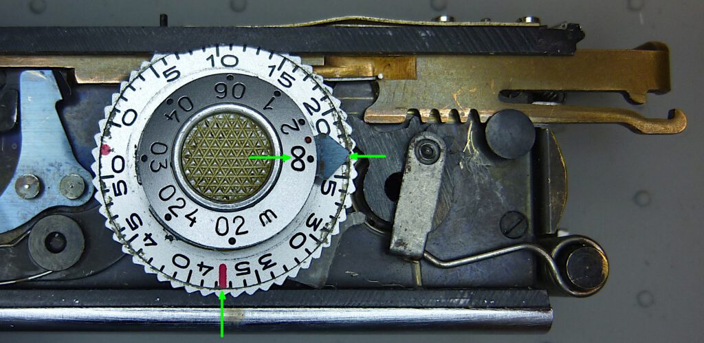
The following three pictures show the position of the lever 10 and the resulting position of the film spool before each film feeding process. You can clearly see that the rotation of the film spool at photo no. 1 turns the longest distance. This has to be the case because there is no film wound on the spool yet and the spool diameter is therefore the smallest. At photo no. 50, the rotation angle of the spool is the smallest because the entire film is now wound on the spool and the spool diameter is therefore the largest:
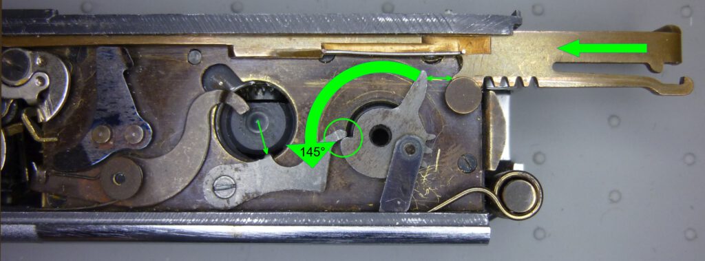
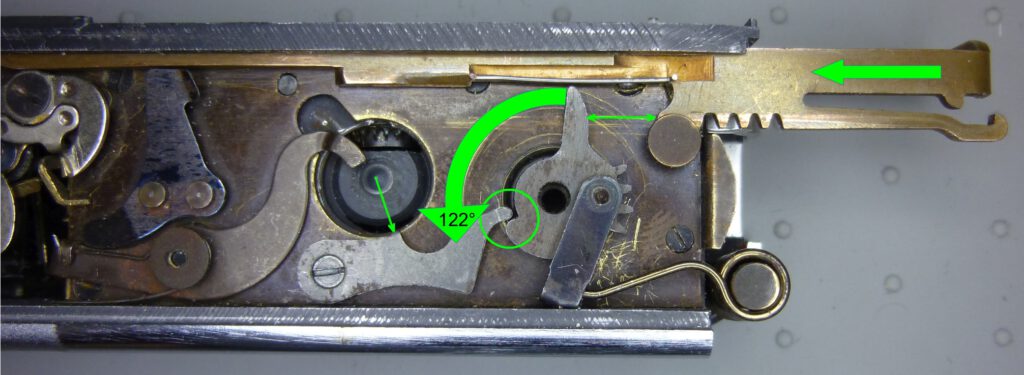
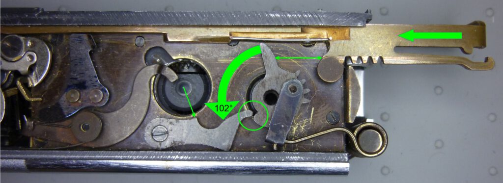
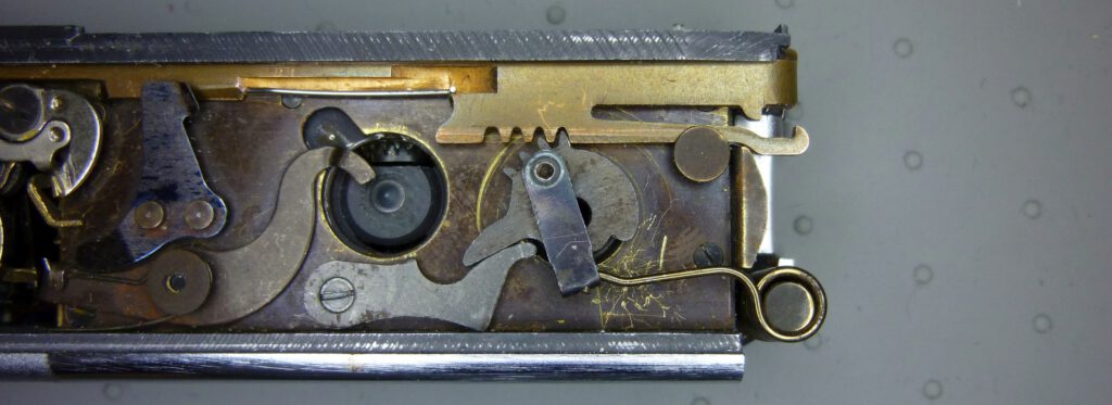
Pay attention to the small green arrow, which indicates the distance of lever 10 specified by the cam. The length of the arrow differs by a maximum of 1 mm in the pictures. This is enough to bring the starting position of the spool to the correct angle (green circle).
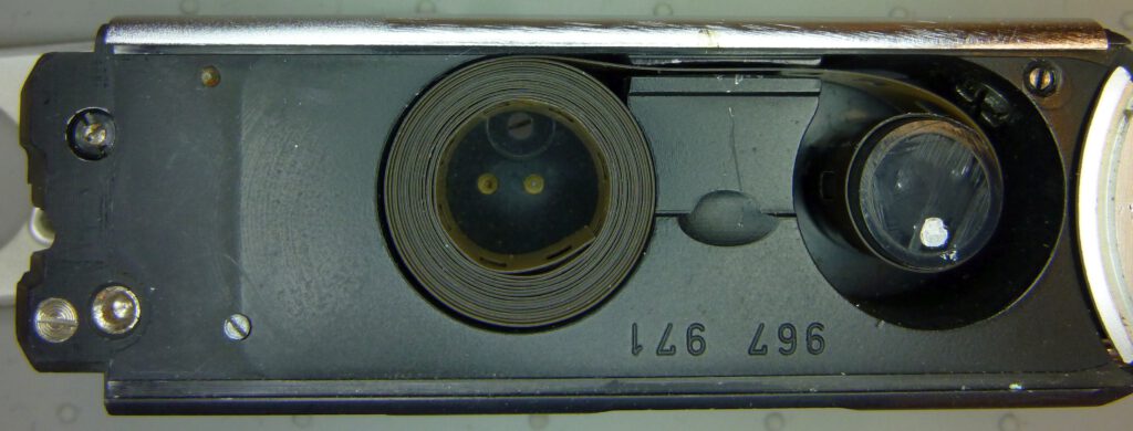
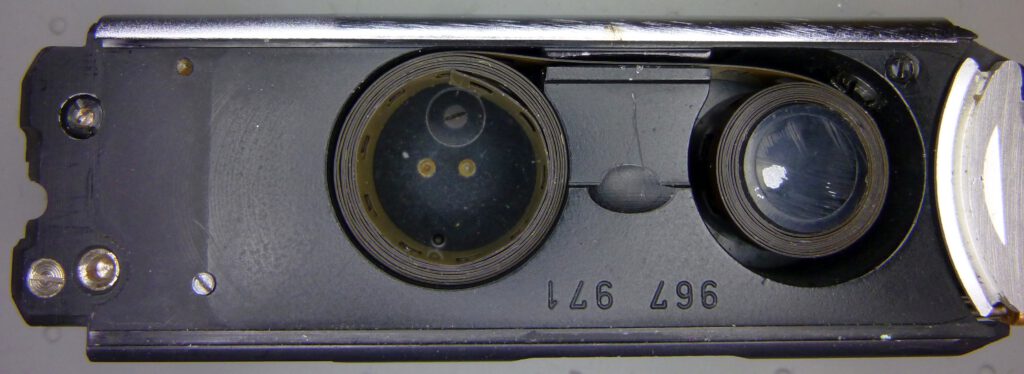
The next three pictures show the spool with the film wound at the beginning, middle and end of the film. You can clearly see how much the diameter of the coil increases due to the thickness of the film. In the end, the diameter increased by 50%, see the third picture. Without the correction mechanism, the distances between the images would be absurdly large. The film cartridge was removed to see the film:
Checking the angles
The diameters of a Minox spool with wound film in the three film feeding situations presented were measured and resulted in the corresponding values in the following table. You can now easily calculate the feed depending on the diameter and angle of rotation of the spool during transport:

feed = angle / 360 * circumference_of_the_spool
feed = angle / 360 * diameter_of_the_spool * π

The spaces between the frames are then calculated, taking into account the negative width of 11 mm:
| photo # | diameter [mm] |
angle [°] |
feed [mm] |
spacing [mm] |
|---|---|---|---|---|
| 1 | 10.7 | 145 | 13.54 | 2.54 |
| 25 | 12.9 | 122 | 13.74 | 2.74 |
| 50 | * 15.4 | 102 | 13.74 | 2.74 |
* diameter estimated

I performed the measurements on an original 36 exp. Minox film using a spool from an original Minox film cartridge. Although the spool has a diameter of exactly 10 mm, I measure a diameter of 10.7 mm at image 1. This is because there are already a few turns of film on the spool at this position due to the lead-in.

If you take into account that the angles could only be determined approximately, the calculated feeds are quite realistic.
You can find the exact dimensions of an original Minox film here.
The mystery of the Minox 15 exp. spool
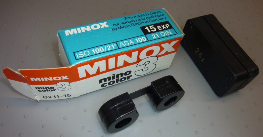
As mentioned, the film spool on the 36-exp Minox films has a diameter of 10 mm. I always wondered why the 15-exp films have a spool diameter of 11.5 mm. These films were only produced by Minox from 1969 onwards.
Julian Tanase (juliantanase.com) pointed me to a 25-year-old post that solves the mystery.
These 15 exp. films were produced for the newer 8×11 Minox cameras, from model C onwards. These cameras have a frame counter that counts down rather than up.
With these cameras the counter had to be set to #151) before inserting the film. This position corresponded to the old position #211) (=36-15). However, in this position the film feeding mechanism assumes a larger diameter than 10 and transports at a correspondingly shorter angle. Minox then took this into account and equipped the 15 exp. films with a thicker, 11 mm, spool. This then leads to correct spacing between the images.
With the Minox A or B, you normally would set the counter to 01) for a 15 exp. film, just like with a 36 exp. film, before inserting the cartridge. In both cases, the spool would have to have a diameter of 10 mm. However, if you insert 15 exp. film into a Minox A or B when the frame counter is at 01), you get spacing that is far too large. Instead, you should insert such a film into position #211).
1) Position should be actually minus 2, because you should transport twice before taking the first picture
Film spool drive
The freewheel
As we have seen, the film spool is rotated when the camera is pushed together and the film is transported. But what happens exactly when the camera is pulled apart?
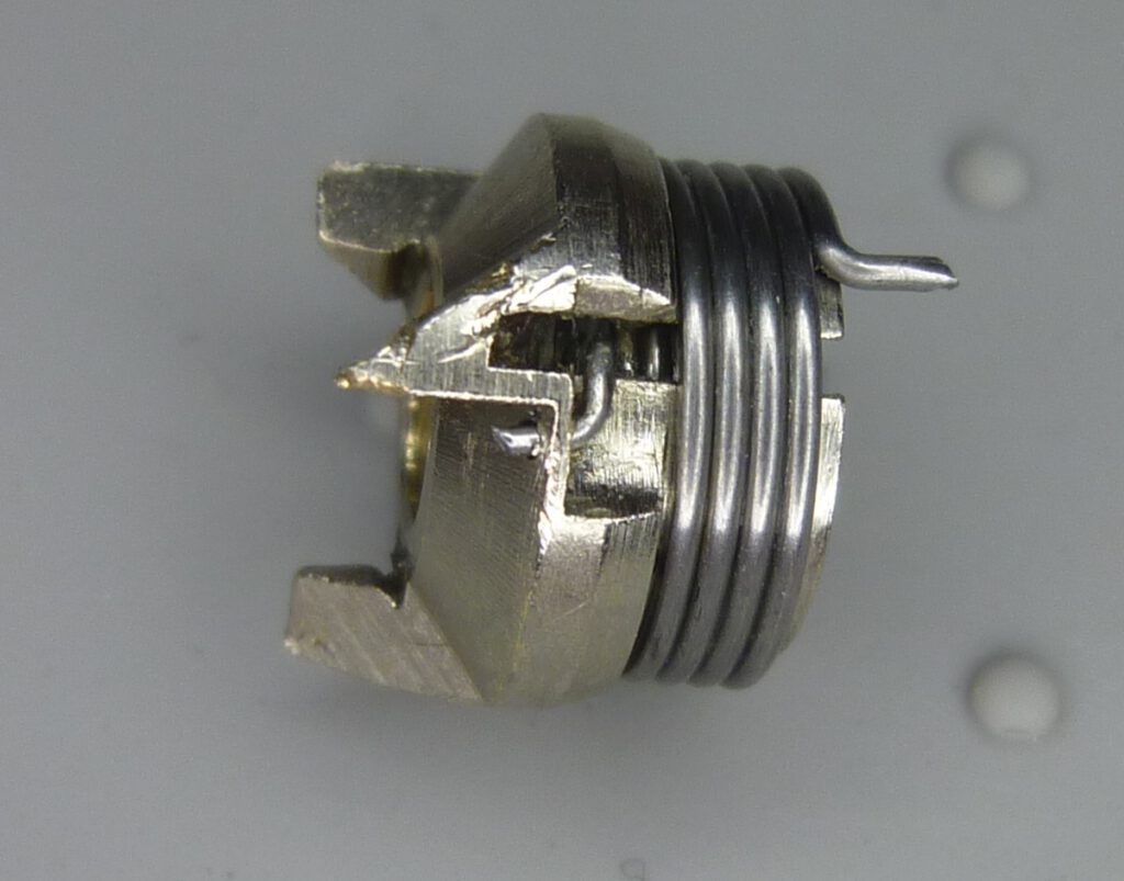
Rack 14 moves to the right and the spool drive 1 (see picture below) rotates backwards to its starting position. However, this backward rotation must not cause the film spool to rotate backwards. For this purpose, the drive is designed as a freewheel. The next picture shows the components involved:
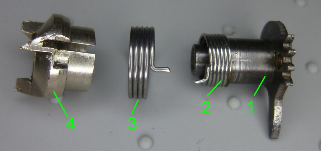
The torque is transferred from the axle of part 1 to the claw via torsion spring 2. The spring 1 is firmly connected to the claw at the left end and loosely pushed onto the axle of part 2 (see picture below). In the forward direction of rotation, the spring wraps tightly around the axle and thus transfers the torque.
In the reverse direction of rotation, the spring expands and detaches from the axle of part 2. No torque is transferred and the film spool does not rotate. In addition, the outer torsion spring 3, which is firmly connected to the housing at one end, ensures that the claw is blocked. When the axle begins to rotate backwards spring 3 wraps tightly around the claw and holds it in position.
When the camera is pushed together, spring 2 blocks and ensures the film transport. When it is pulled apart, spring 3 blocks the claw and thus the film spool. Once again an ingeniously simple and space-saving solution.
Servicing the film spool drive
Please read our Legal Disclaimer before proceeding.
The assembly can be cleaned and lubricated. To do this, however, it must be disassembled. Before, the Minox housing must be opened. To do this, the control plate must be removed. You can find the description of this process here.
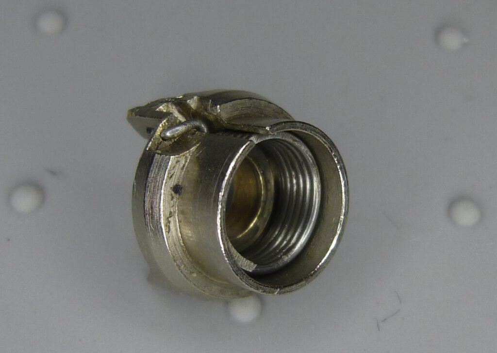
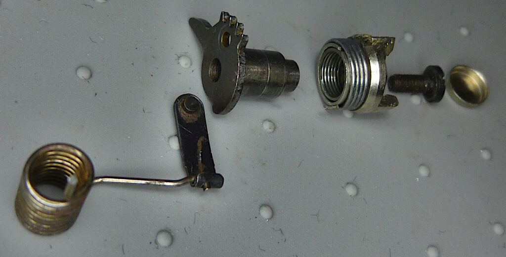
The film spool drive consists of several parts. You can take this assembly apart to lubricate the sliding surfaces. To do this, press the torsion spring, see picture below, upwards and pull it out of the lug. Be careful, the spring is under high tension! You can then pull the lug out of part 2a.
Now turn the camera over so that you can see into the chamber of the film cartridge. Then use a screwdriver to lever the protective cap off the top of the claw. Underneath there is a screw which you now unscrew. Then pull the claw out upwards.
Turn the camera over again and pull part 2a out of the housing. This completely disassembles the assembly (apart from the torsion springs in the claw). Here you can see the individual parts:
All sliding surfaces can now be lubricated with grease. Because of the proximity to the lens, I would not use oil here, as it could easily spread uncontrollably in the surrounding area.
I recommend only cleaning the two springs of the freewheel, but not lubricating them. Lubricant would be harmful here because it would reduce the transmission of torque.
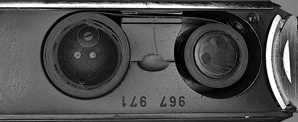
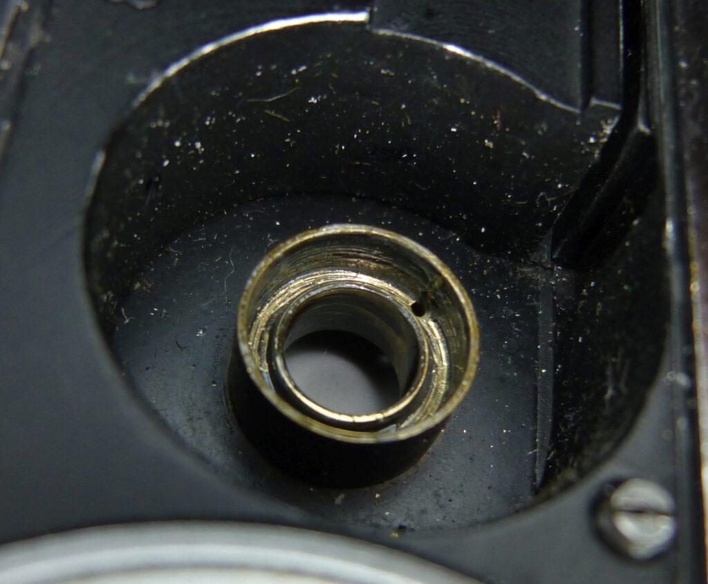
The bearing point of the spool is clearly visible from the film chamber. Note the small hole into which the inner torsion spring of the claw must later be inserted:
The film feeding problem
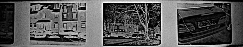
It happens that the presented mechanism does not work correctly. Then the distances between the negatives are too small, resulting in the negatives overlapping on the film:
Unfortunately, this defect cannot be checked with the camera unopened. You only recognize it once you have exposed a film. There are two causes of this malfunction, one harmless and one more difficult to fix.
Please read our Legal Disclaimer before proceeding.
Cause 1: Film inserted incorrectly
The harmless reason for this is that you operated the camera incorrectly. It is clear from what has been said that the correct amount of film transport depends on the right position of the image counting disc. That’s why the operating instructions specifically point out how important it is that the frame counter must be at image #0 (actually 2 images before that) before inserting a new film. Now it is clear to us why this has to be the case. Otherwise cam 9 would be in the wrong initial position. The mechanism would then assume an incorrect spool diameter and transport an incorrect (too short) length of film.
The fix is simply to load the film correctly.
Cause 2: Frame counter transmission defective
If the negative distances are incorrect despite correct operation, there is an error in the mechanism described. In my experience, lever 16 then jumped out of its bearing. Then the number of images is no longer transferred or the lever blocks the spool. As a result the film transport is too low and the negatives overlap.
This defect can actually only occur if someone has opened the Minox and manipulated it improperly. When the housing is open, the lever can come loose. If you then fix it incorrectly, e.g. without the spring being reinserted, exactly this malfunction occurs.
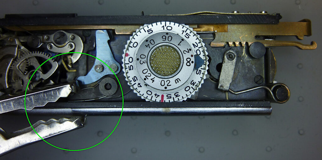
In order to reinsert lever 10 correctly, the Minox housing must be opened. To do this, the control plate must be removed. You can find the description of this process here. The view inside then looks like this:

First the combined disc must be removed. It is important to know that it consists of two independent discs which form an inseparable unit. Firstly we have the outer image counting disc and secondly we have the inner distance dial. They are both rotatably connected to each other. Before removal, the distance dial must be turned to the “infinity” setting as shown in the picture above.
Now push the image counting disc all the way back under the edge of the housing. You can see in the picture above how the disc at image number 10 slides under the edge.
Disassembly
Before you can take the whole disc out, the two levers under the disc must be relaxed. The lever 10 is relaxed by pushing the rack halfway in from the right, as shown in the picture above.
The other lever comes from the left side and is connected to the viewfinder to provide parallax compensation. The best way to relax this is to fix the lever on the front edge of the housing with a spring clip:
Now the entire disc is free of the two levers and you can lift the front edge (where the red line is) and remove the entire wheel. Then you can see the two levers which were hidden by the disc. The lever on the left engages a cam on the distance dial and moves according to the set distance. This realizes the parallax compensation of the Minox viewfinder.
For safety reasons you should first mark the position of the crown wheel of the lens so that you can always find the “infinity” focus point again later (gray dot).
The repair
Now we come to the actual repair. If there are problems with the spacing of the negatives, it is probably because lever 10 has come off its mounting and is lying loose under the disc. It prevents the correct starting angle of the spool before the transport process.
Note that lever 10 only sits loosely on the screw. The screw is actually just a pin on which the lever rotates. So the screwhead does not fix the lever. It is just pushed over the screw.
During normal operation of the camera, the lever cannot actually be released because it is held in place by the image counting disc above it. However, if someone opens the camera body and pushes the rack back and forth, e.g. in order to cock the trigger, the disc can fall out. If he didn’t put it back in correctly, the lever could slip out of the fastening.
Now put the lever 10 back in correctly so that it looks like the picture above.
By the way, this lever is the only part of the Minox that can turn freely without being fixed by a spring. That’s why even a completely intact Minox rattles quietly when you shake it. This was even pointed out in the Minox publication Der Minox Freund no. 15 (1964) because customers were unsettled by the rattling and suspected a defect. It says:
“Every Minox must rattle quietly when shaken close to the ear in a certain direction. The noise comes from an important part inside the camera, the film compensation lever, which – together with other parts – ensures that despite increasing spool thickness, the image spacing remains the same until the end of the film. This part must be freely movable if it is to perform its function properly.”
Now you can put everything back together again in the reverse order.
Important: When reinserting the disc, pay attention to the correct position of the image counting disc and distance dial, as shown below, i.e. red line of the image counting disc at the front, symbol “infinity” of the distance dial aligned exactly to the right. The end stop of the distance dial (the black triangular piece of sheet metal) must also be on the right:
Check the repair
A verification of the repair can only be done by exposing a film and checking the negatives.