The Minox shutter speed test device presented here and the realization were a joint effort with my friend and colleague Martin. He developed the necessary hardware and, above all, wrote the exquisite software for it. My contribution was merely to formulate the requirements for the solution. Martin has been researching and teaching in the field of microcontrollers for decades and has written countless publications on the subject. Thanks for everything!
Page Contents
Why a Minox-specific test device?
Analog cameras project a light image through a lens onto a light-sensitive film, which records this image. This process takes different lengths of time depending on the brightness of the image. For this purpose, such cameras have a mechanical, time-controlled shutter that interrupts the light path in the camera after the exposure time.
Testing the proper functioning of camera shutters is a critical aspect of photographic technology, as the shutter speed significantly influences exposure time and image quality. Over time, various testing methods and devices have been developed to ensure the accuracy and reliability of shutters. However, there is another important aspect. If the measurements show large deviations from the to-be values, you can draw conclusions from the measurement results as to which parts of the mechanism are not functioning correctly. This is an important aid for subsequent repairs.
Since Minox cameras are not accessible from the rear, the usual measuring devices for determining shutter speeds cannot be used, as they are based on the illumination of the lens from the front and the measurement of the incoming light from the open rear. Here I will show you a method I have devised for measuring Minox shutter speeds very easily, quickly and reliably.
To better understand the problem, it is useful to first get an overview of how shutter speeds have been and are measured. But if you know the contexts, you can jump straight to my solution.
Historical and up-to-date shutter speed measurement
Here we only consider methods that measure shutter speeds directly. We do not consider exposure bracketing and evaluation of the results here, partly because the result also depends on the film used.
The development of shutter testing methods began in the 19th century with simple visual and manual techniques. Shutters (e.g., flap or slide shutters) were tested by visually observing their operation. The shutter was manually triggered, and the operator checked whether it fully opened and closed. This method was imprecise and often failed to detect subtle issues like uneven movement or partial closures.
Photographers also checked shutters through observation and auditory tests to ensure they fully opened and closed. With the advent of mechanical and later electronic technologies, more precise devices were developed for use in camera production and repair.
Sutter speed test device for photographic shutters, 1908
The earliest device known to me, the “Speed Testing Device for Photographic Shutters,” was introduced in 1908. It consisted of a lighted tube in a rotating drum. The camera was positioned in front of the device and the shutter speed was calculated by the number of dots on the negative, each dot corresponding to a known time interval, and the device consisted of a horizontally mounted lighted tube located within a rotating drum “F.B.”.
The shutter to be tested is attached to a camera and positioned in front of the device, focused on a slot in the barrel. As the drum rotates, the shutter is released and light passes through the slit, creating a negative image on a photographic plate.
This negative image shows a sequence of dots, each dot corresponding to a specific time interval defined by the rotation speed of the drum. The length of the exposure is calculated by multiplying the number of dots by the time value per dot, which is derived from the drum speed. For example, if the drum is set so that each dot corresponds to 1/1000 second, and the shutter is set for 1/100 second, the negative should show 10 dots. However, if it shows 20 dots, this means that the shutter was actually open for 1/50 second, indicating an irregularity.
You could certainly test Minox shutters with this device. However, the device is large, no longer available and cumbersome, as you would have to develop a film for each measurement.
Incidentally, the same principle is also used by a method for amateur photographers described in Popular Mechanics 1967, in which a record player is used instead of a drum.
Camera shutter tester, 1937
The advent of electronic components introduced photoelectric testing devices. A light beam passes through the shutter and strikes a photosensitive sensor. The first methods to measure light electronically were developed in the 1930s. In J. D. Kelley’s patent, a photoelectric cell 17 is used for this purpose. Position 13 is the shutter to be tested.
This device would be unsuitable for shutter metering with a Minox, as you measure from the back of the camera, which is not accessible with the Minox.
Today’s state of the art
Professional shutter testers
How analog used cameras are tested today with professional standards is described in detail and easy to understand here.
A product described on this website for level 2, the Photoplug, is one of the most cost-effective and usually sufficiently accurate solutions for central locking systems. However, you should buy the special light sensor in addition to the smartphone app, as the acoustic measurement does not work reliably. I have successfully measured Minox shutters with this system with the appropriate modification, see here.
DIY solutions
Current DIY shutter tester projects using Arduino and Raspberry Pi offer a range of options for photographers and electronics enthusiasts. Arduino projects are more common and beginner-friendly. A recent example is the 2024 Laser-Powered DIY Shutter Speed Tester.
Raspberry Pi projects, particularly using Raspberry Pi Pico, are less frequent but cater to advanced users, with notable projects from 2023 demonstrating their potential.
Conclusions of the current status
As far as I know, all current products and solutions are based on the transmitted light method, in which light (visible light, laser light or infrared light) is sent through the front of the camera lens. This is registered by a corresponding sensor as long as the shutter is open.
Solutions and projects are available both for central shutters as well as for focal plane shutters. Since two independently controlled curtains move past the film negative in focal plane shutters, both must be precisely synchronized. With slow shutter speeds (e.g. 1/60 s or longer), the first curtain opens the shutter completely first. After the set time has elapsed, the second curtain closes the shutter again. A faster shutter speed can be achieved by starting the second curtain before the first curtain has reached its end position. Depending on the selected exposure time, the second curtain is started earlier so that a narrower slit is formed which moves across the negative. A common problem arises when the speed of one or both curtains is not constant. The slit width then changes during the exposure time. In extreme cases, the second curtain can even overtake the first. In order to measure this type of error, at least two sensors are required for focal plane shutters.
In any case, none of these solutions can be used for shutter metering on a Minox 8×11 camera.
Shutter speed test device for Minox 8×11 cameras
How can we achieve the goal of measuring the shutter speed of a Minox 8×11 camera in a simple way – especially without dismantling the camera?
Preconditions
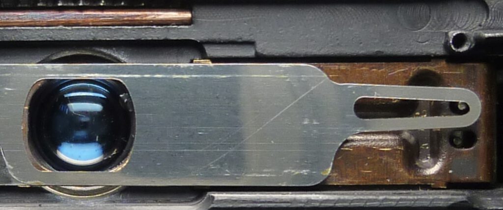
We can use three features of a Minox for our purposes. Firstly, the shutter blades are at the very front of the lens, directly behind the protective glass. Secondly, the blades have a silver reflective surface:
shutter cocked, blade 1 covers the lens
As soon as the shutter opens the lens, significantly less light is reflected at this point:
shutter open, blade 2 opens the lens
Thirdly, the Minox has a guillotine shutter, not a focal plane shutter. You can see this clearly in the following animation. At all shutter speeds – even the fastest ones – the second blade only starts when the first one has fully opened the shutter:
If you want to know more about how the Minox shutter works in detail, read my article here.
Solution: A Minox shutter speed test device
Requirements
The most important requirements for the project were:
- accurate and reproducible shutter speed measurements for all 8×11 Minox cameras of the main series (Riga VEF, A, B, BL, C, LX, AX)
- easy to use
- fast measuring process
- to be operated without a PC or smartphone
- graphic display of the measuring process
- direct display of the measured shutter speed in 1/s and in ms
- insensitive to interference from ambient light
- own power supply
- small size, easy to transport
- optional: sensor replaceable so that through-light measurements can also be made
Hardware
From points 1 and 2 we can take advantage of the fact that light The measuring devicedirected at the camera’s front is strongly reflected by the blades as long as the shutter is closed. When the shutter is opened, much less light is reflected. A light sensor looking at the blades can register this difference in brightness.
Because of point 3, we only need one sensor, because the shutter is fully open at all exposure times.
An elegant version of this principle now consists of an electronic component that combines the light source and sensor in one housing.
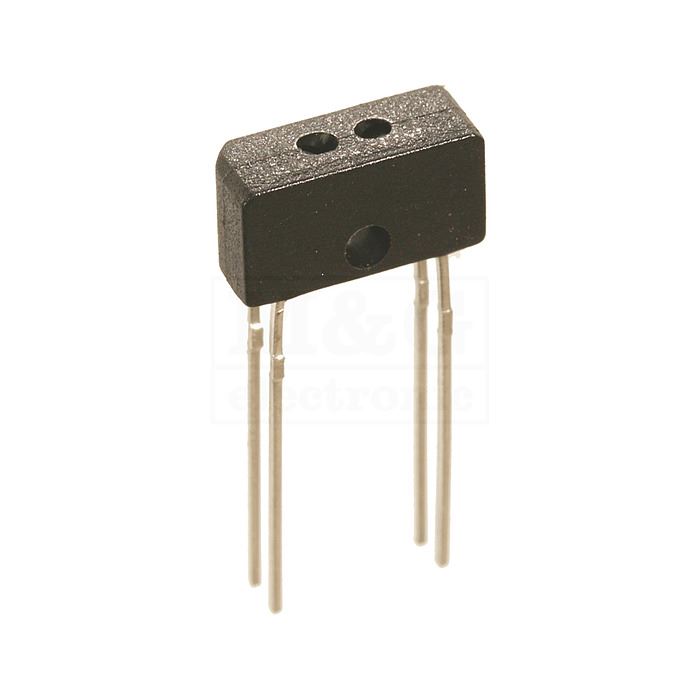
The ITR9904 is a so called opto interrupter used to detect objects or movement without touching them. It has two main parts: an infrared LED which sends out invisible light and a phototransistor which detects the light. The LED and phototransistor are placed facing each other with a small gap in between.
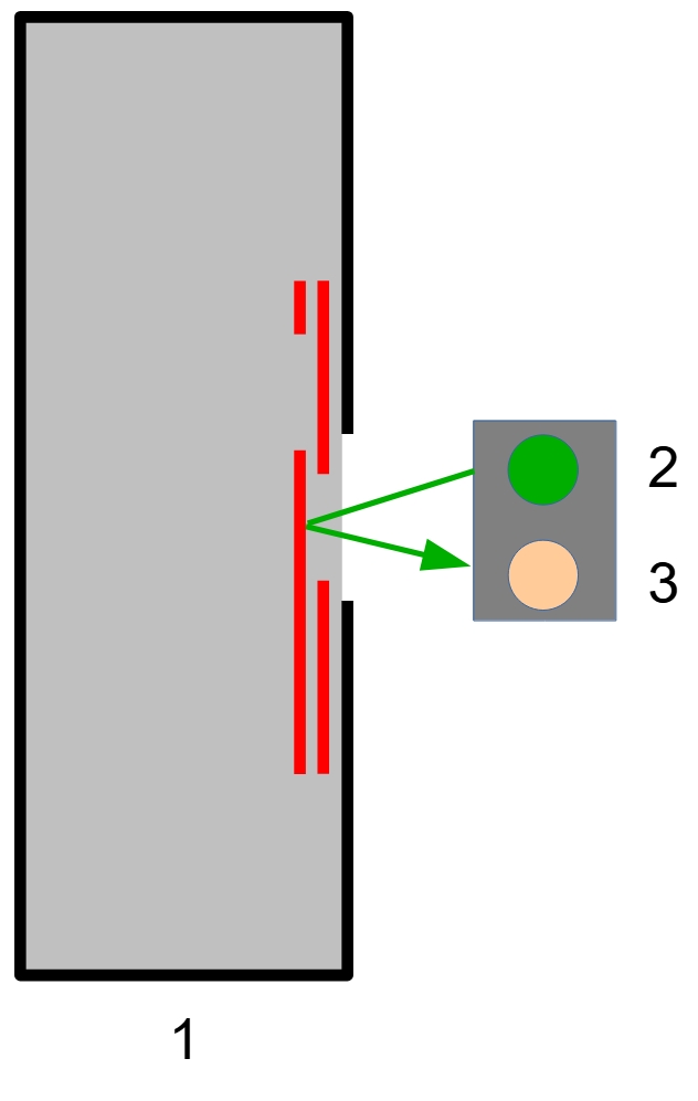
shutter blades (red) in cocked position,
2: Infrared LED, 3: phototransistor
The ITR9904 can be placed directly in front of the lens window of the Minox. The opto interrupter works optimally at a distance of 3 mm. As the blades are approximately at this distance behind the lens window, the position is ideal.
When the shutter is closed, the phototransistor detects the reflected infrared light and the phototransistor emits a high signal. As long as the shutter is open, the reflection is low and the voltage at the sensor drops sharply.
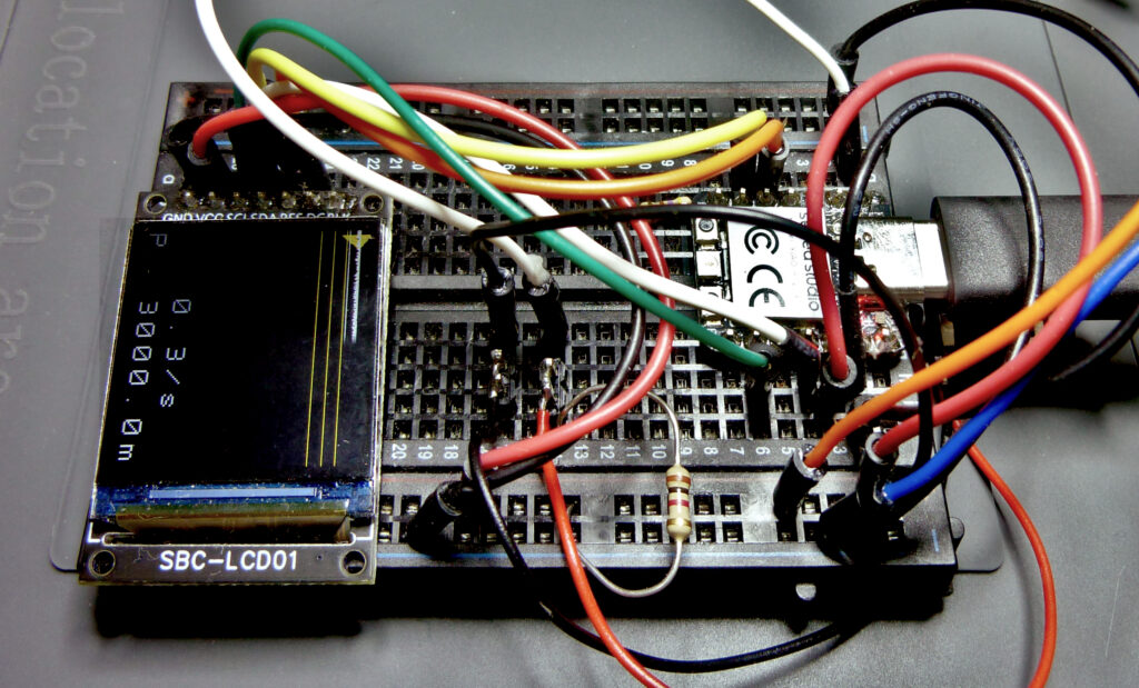
The sensor signal must then be evaluated by a corresponding logic to calculate the associated time periods. This is done with a Raspberry Pi microcontroller board, in our case a Xiao RP2040, dual-core 133 MHz, 2 MB. The output is shown on a Joy-It SBC-LCD01 graphic display.
In order to use the tester for different measuring methods, the connections for the sensor C1 are led out via a 4-pin jack plug socket. Power is supplied via the USB port of the controller. For example, a power bank can be connected there.
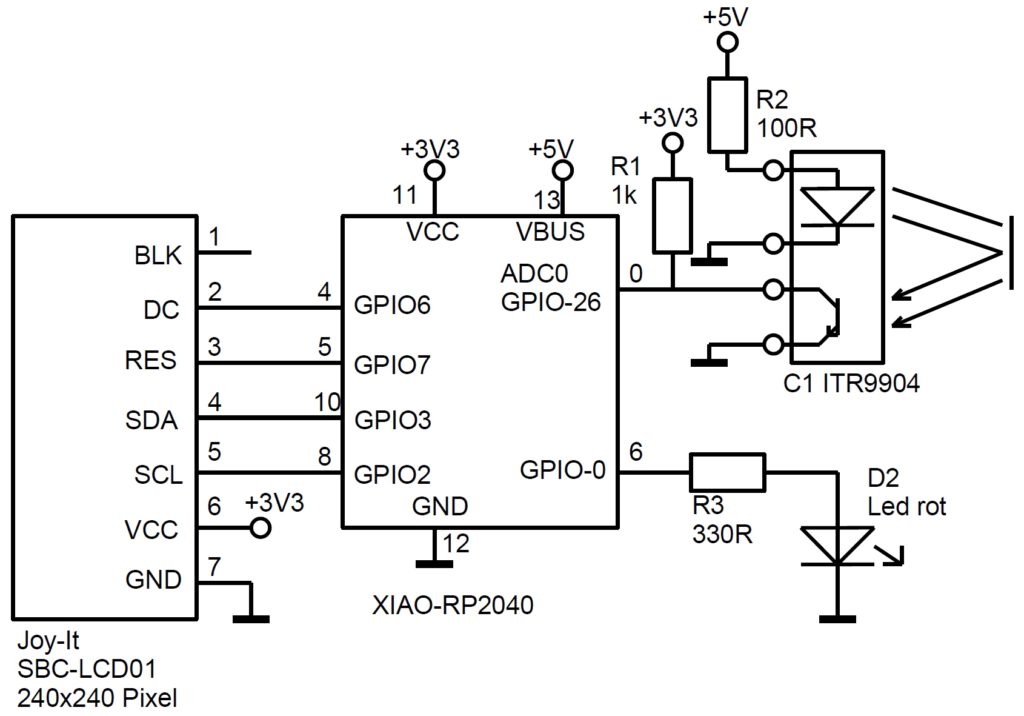
Circuit diagram of the ShutZ shutter speed tester
The circuit diagram shows the combined ITR9904 sensor for the Minox measurement. Instead, a phototransistor and an LED can also be connected separately for the through-light method. The LED is then located in front of the lens, the phototransistor on the open back of the camera.
The red LED D2 is a practical additional indicator when carrying out the measurement. It lights up as long as the opening of the shutter is detected.
Software
The hardware components together cost less than 15 dollars, but the software is priceless. It uses the A/D converter with 50000 samples per second, which is serviced via an interrupt routine. This is necessary so that no measured values are lost during the graphical display.
As different sensors and camera types are to be used, it was necessary to automatically determine the quiescent level. The signal curves for the Minox reflex measurement and the transmitted light measurement have opposite signs. This is also automatically recognized and taken into account. The opening or closing of the shutter is then detected via a Schmitt trigger.
The software is written entirely in C using Visual Studio Code.
Display
The display contains all the important information about the measurement:
The white curve shows the measured brightness. The quiescent level, to which the switching thresholds for detecting the shutter function refer, can be recognized by the yellow triangle on the left edge. The middle yellow thin line is the actual switching threshold. The lines above and below it show the hysteresis range during the time measurement when the shutter is open. The brightness must remain within this range so that the shutter is still considered to be open.
The thick line at the top shows the determined shutter status over time. Yellow means shutter closed, red means shutter open. The LED on the device also lights up during the red time range.
The time period shown on the display is always 2 seconds.
The result of the last measurement is shown in the two bottom lines of the display in fractions of a second (1/s) and in milliseconds (ms). The letter “P” at the beginning of the last line indicates that a reflex measurement (Minox method) has been detected. For transmitted light measurements, the letter “N” appears.
Verification of the Minox shutter speed test device
The AD converter records the sensor value with 50000 samples/sec, so that a shutter speed of 1/1000 sec is theoretically recorded with a resolution of 1/50 = 2%. To check this, we built a second controller board that generates light signals of a precisely defined duration. These signals can now be measured by the shutter speed tester.
An additional controller board generates test pulses of a defined length with the accuracy of the processor clock frequency. It feeds an LED that illuminates the sensor of the shutter speed meter. It can now be checked whether it is measuring the correct length. The accuracy achieved was approximately +/-2 samples, i.e. +/-40 microseconds, which is accurate enough for all practical purposes. This also verifies that the phototransistor in the circuit is fast enough for this application.
The measuring device
The measuring device consists of the actual shutter tester, the sensor, the camera holder and the power supply unit. The device is switched on via the power supply and then continuously measures the brightness at the sensor.
After a shutter function is detected, the display shows the determined shutter speed. This indication remains on the display until a new shutter function is detected. In this way, the camera can be triggered again and again and the last shutter speed is displayed.
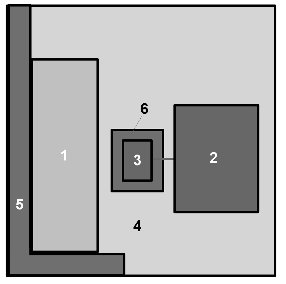
Camera 1 to be tested is placed against the stop 5 on two sides. This means that the position of the lens window in front of the sensor is set correctly for all Minox models.
Sensor 3 is then mounted on the base 6 directly in front of the lens. The sensor is connected to the evaluation unit 2, which contains hardware, software and display.
All components except the camera are fixed to the base plate 4. The power bank for the power supply is not shown.
In practice, the setup looks like this using the example of a Minox LX with a preset shutter speed of 1/125 s:
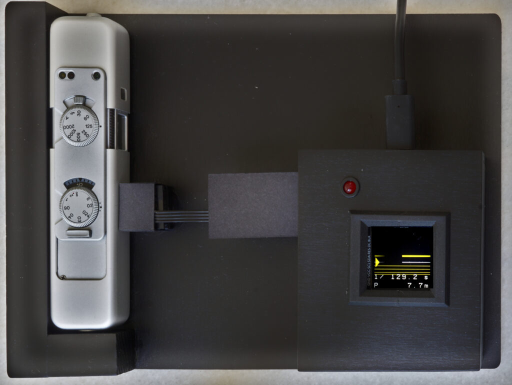
A measured shutter speed of 7.7 ms or 1/129 s is shown. Although the Minox LX has an electronic shutter control, there can still be inaccuracies in the electronics and the mechanical shutter blades. In any case, this measurement shows a very good accuracy of the camera.
The measuring process
The actual measuring process is simple and quick:
- Switch on the power supply to the meter.
- Take the camera in your hand, set the exposure time to be measured and cock the shutter.
- Place the ready-to-shoot Minox on the metering device and align it with the stop.
- Wait until the red indicator LED is off ( the display shows the quiescent level and a constant brightness curve). Then release the shutter.
The measured exposure time appears.
The following video shows this process for measuring three different exposure times with a Minox B:
Results, set value vs. measured value:
1/2 s vs. 1/2 s
1/100 s vs. 1/267 s
1/1000 s vs. 1/1326 s
A practical example
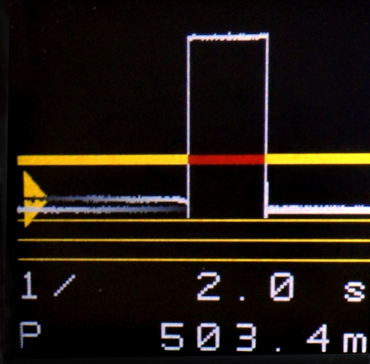
With our measurement setup, shutter speed curves for the Minox can be determined, which show the deviations from the ideal values and exceedances of the tolerance values. In this example, a Minox A IIIs is tested with all shutter speeds. The measurement setup shows the situation immediately after measuring the preselected shutter speed of 1/2 s :
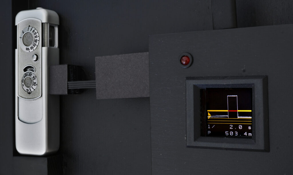
The measured brightness curve (white curve) and the recorded shutter opening time (red line) are plotted over time. The resulting shutter speed of 503 milliseconds or 1/2 s is displayed below. The camera works perfectly for this setting.
The measured values for all other shutter speeds are shown in the following diagram:
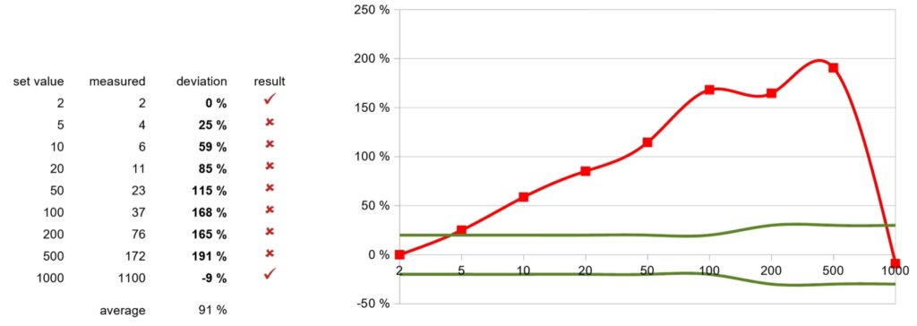
The faster the shutter speed, the greater the deviations from the set values. All measured values except 1/2 s and 1/1000 s are outside the (green) tolerance band.
Conclusions can be drawn directly from the curve about the causes of faults in the shutter mechanism, e.g. in the escapement, resinification of the oil in the lubrication points or deformation of the shutter plates. The fault can then be repaired with the appropriate expertise.
For example, the following conclusions can be drawn from the diagram shown:
- Since the longest shutter speed of 1/2 s is correct, the escapement that controls the time delay is in working order. If it works accurately for the longest time measurement, it will do so even more for the shorter times. However, the tension of the spring in the barrel may be too low. This would lead to a slower start-up of the escapement. With long shutter speeds, the short start-up phase does not have such a significant effect. However, the shorter the shutter speed, the greater the proportion of the start-up phase. As a result, the deviations increase in percentage terms. As the 1/1000 s skips the escapement, this shutter speed is not affected by the error.
- The shortest time of 1/1000 s is also correct. The escapement is no longer involved here. What is important here is that the two blades run at maximum speed in their slots and that their tension springs have sufficient tension. This appears to be the case in our example.
- If points 1 and 2 are ok and the medium shutter speeds are still outside the tolerances, the only remaining cause is the connection between the release lever and the blades. This connection consists of the two pins of the lever that engage in the eyelets of the blades. In our case, the assumption would be that the eyelets of the plates are bent against each other. Depending on the direction of the bend, this can lead to either longer or shorter exposure times.
A slip stick effect would also be possible due to too much roughness of the pins. Or the bearing of the lever is stiff, so that it begins to move more slowly than it should. Both causes have a greater effect at faster shutter speeds. We can see this in our curve. The following picture shows the two pins on the right as they hold the blades over the eyelets when the shutter is cocked:
The next video shows the real situation in which the blades sit in the guide and are covered by it. Pay attention to the movement of the pins as they release the blades one after the other:
Conclusion of the shutter speed test:
The first thing you should look for during the repair is whether the blades are bent in the area of the eyelets, where they are held by the pins of the shutter control. Then you should take a closer look at the pins, especially their surfaces. Thirdly, the lever bearing should be cleaned and relubricated.
I recommend remeasuring the shutter speeds after completing each point of the repair. This is also possible with the front panel open (see video above) and will provide information about the real cause.
Conclusion
Testing the shutter speeds of Minox 8×11 cameras is very quick and easy with a special device. This Minox shutter speed test device was built inexpensively as a DIY project.