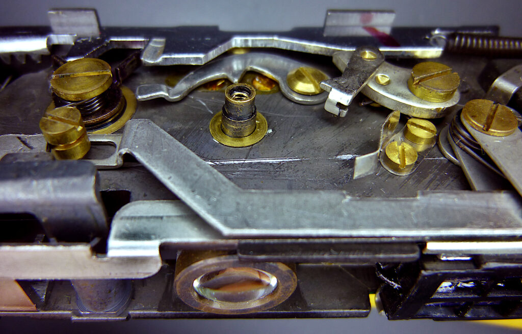
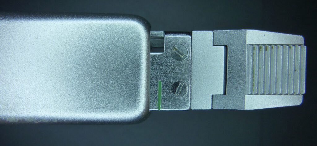
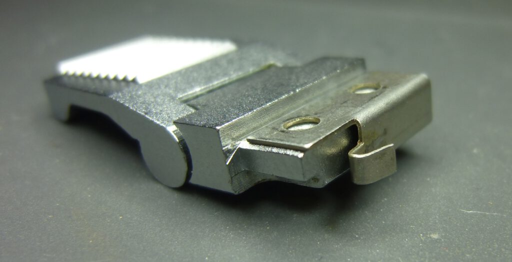
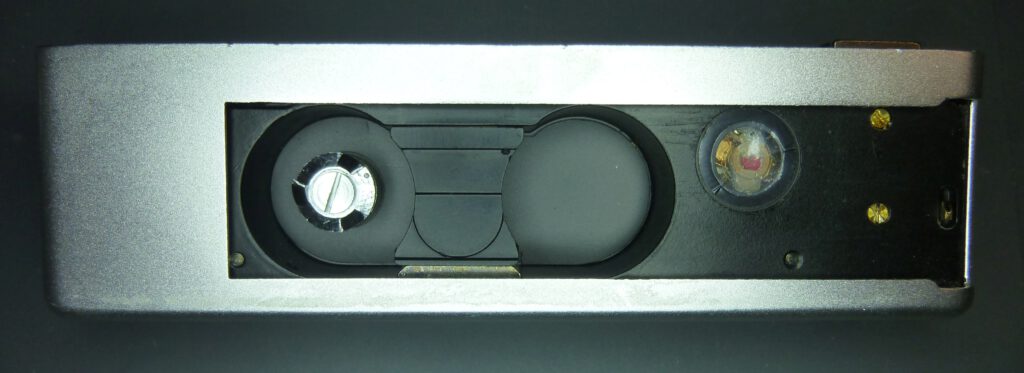
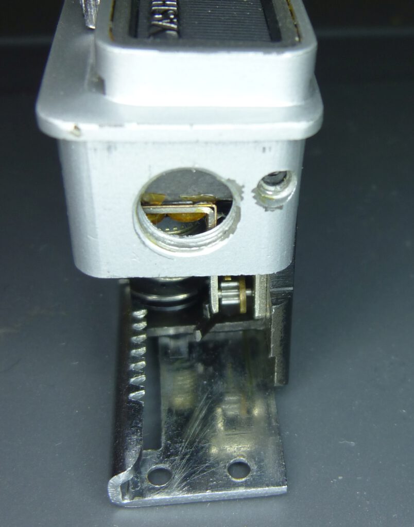
Compared to the Minox, the Yashica atoron is easy to open and maintain. The shutter mechanism in particular is very easy to clean if the shutter opens too slowly or not at all. Problems with the shutter blades – the major weakness of the Minox – are not really to be expected. This is because they are very robust and well protected. The selenium cell of the light meter is easy to replace; the problem is rather where to get a replacement cell.
This article would not have come about without the discussions with and advice from Rainer (blende-und-zeit.sirutor-und-compur.de). Many thanks to him.
Many thanks also to ic-racer from the Photrio forum, without whom I would not have been able to open the camera. His very comprehensive thread about the atoron disassembly and replacement of the selenium cell gave me crucial information for repairing it.
Rick Oleson, who wrote the famous article “How the Minox shutter works” many years ago, has now also written a great guide to the complete inner workings of the atroron. As always, he has provided them with excellent drawings, which often explain things better than photos. You can find this PDF document among many others here.
Page Contents
Open the camera
There are no screws on the housing of the atoron on how to open the camera. However, there are detailed instructions online here, which I followed.
First I unscrewed the film advance lever. You pull it out, but not completely. You can hear it click into place at short intervals. When it clicks into place for the last time, you stop pulling. In this way, the lever remains in this position:
Now you can loosen the two slotted screws. Be careful, a spring plate on the back of the lever will also come free and fall down.
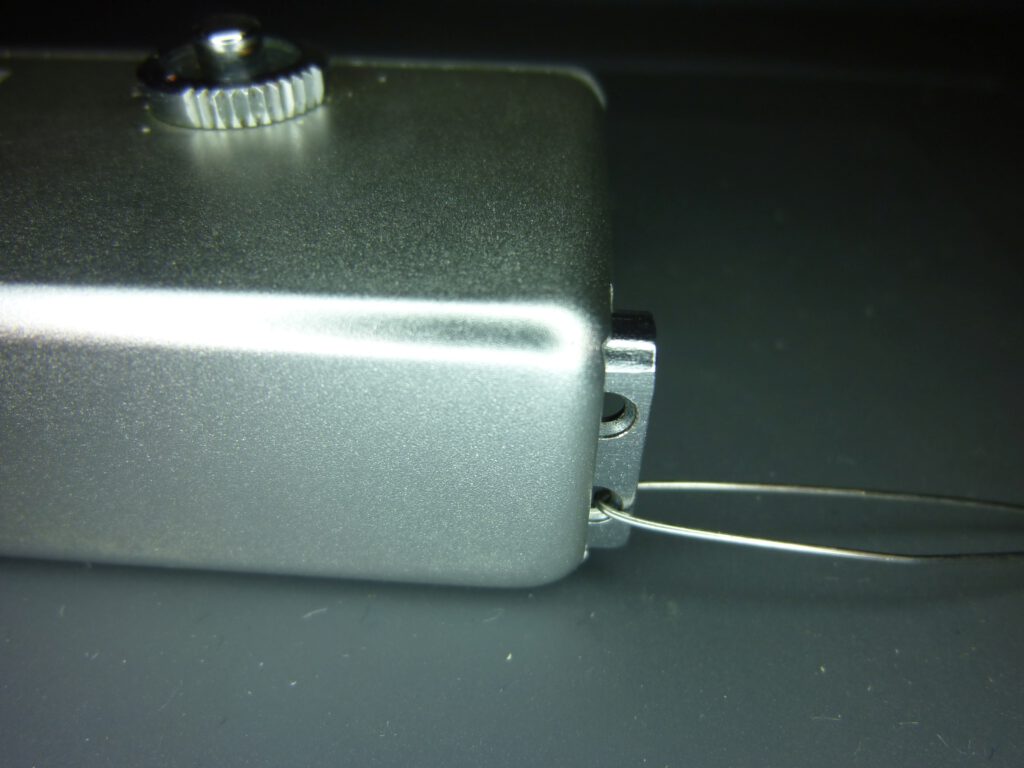
I secured the end of the lever with a piece of wire so that I could pull it out of the housing if necessary. I then pull the lever as far as it will go and let it slide back into the housing.
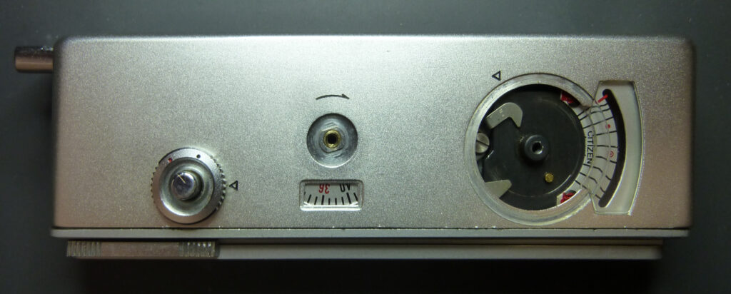
Next I removed the dials for the frame counter and the light meter. This requires a tool for two-hole screws. I used a divider for this.
Next, I loosened the two-hole nut at the lower end:
The dial for the frame counter consists only of the screw and the wheel. However, four individual parts are hidden under the exposure setting wheel:

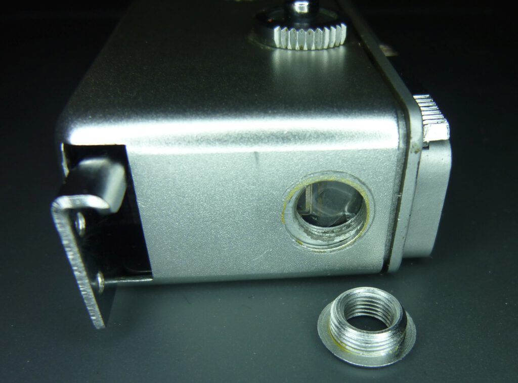
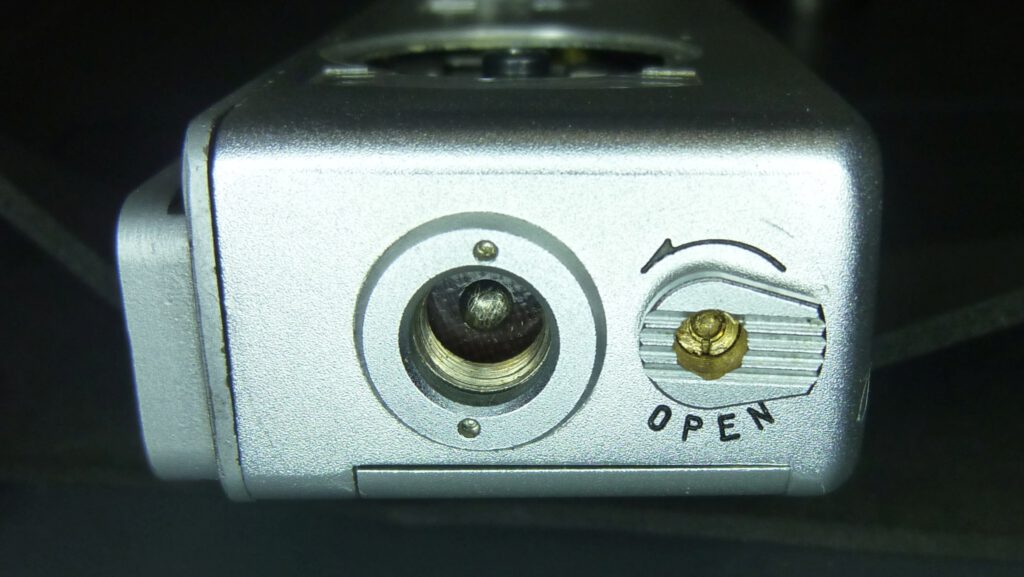
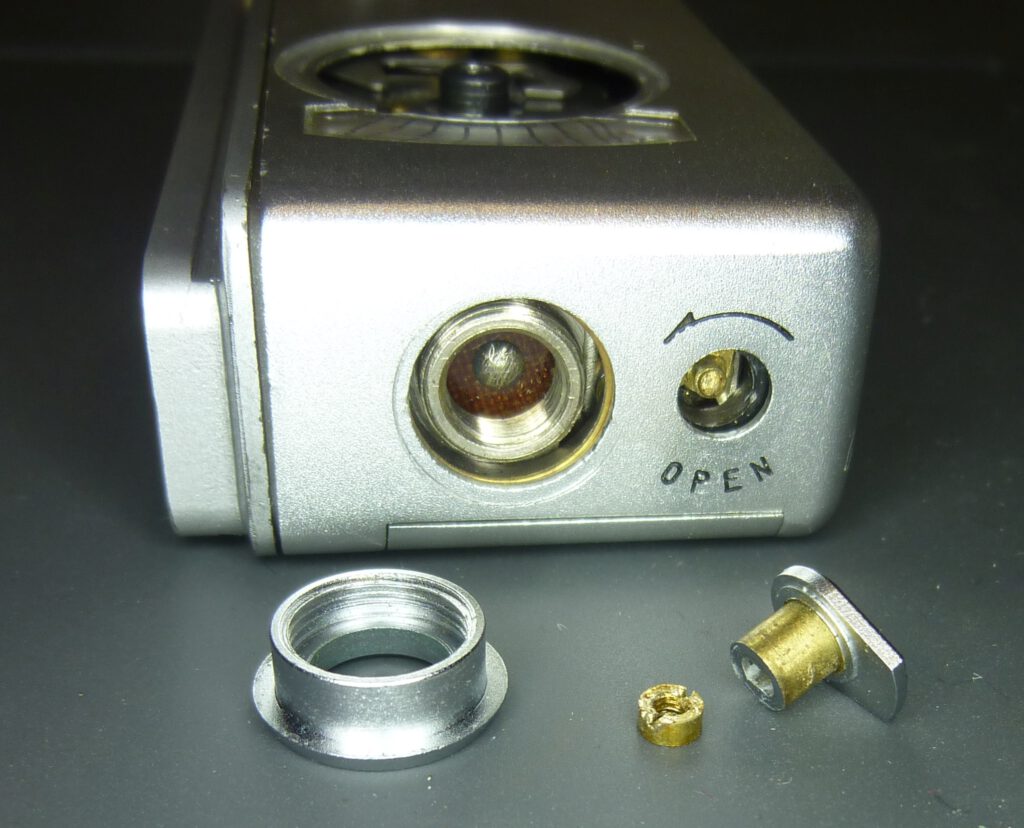
There is a two-hole nut on the top of the camera with which the flash can be screwed on. We also have the back cover lock knob next to it. This is the most difficult to loosen.
There is a tiny slotted brass nut under the black cover in the middle of the knob. To loosen this, I made a suitable tool from a 3 mm wide slotted screwdriver. I milled a U-shape in the middle of the blade. But even with this tool, it was not easy to loosen the nut because it was stuck. In the end it worked with patience and dosed force.
Note the small brass threaded pin in the housing. The brass nut was previously screwed on there.
The housing can only be removed when the back cover is removed first. To do this, turn the back cover lock knob in the “pull” direction and hold until the cover is completely pulled out:
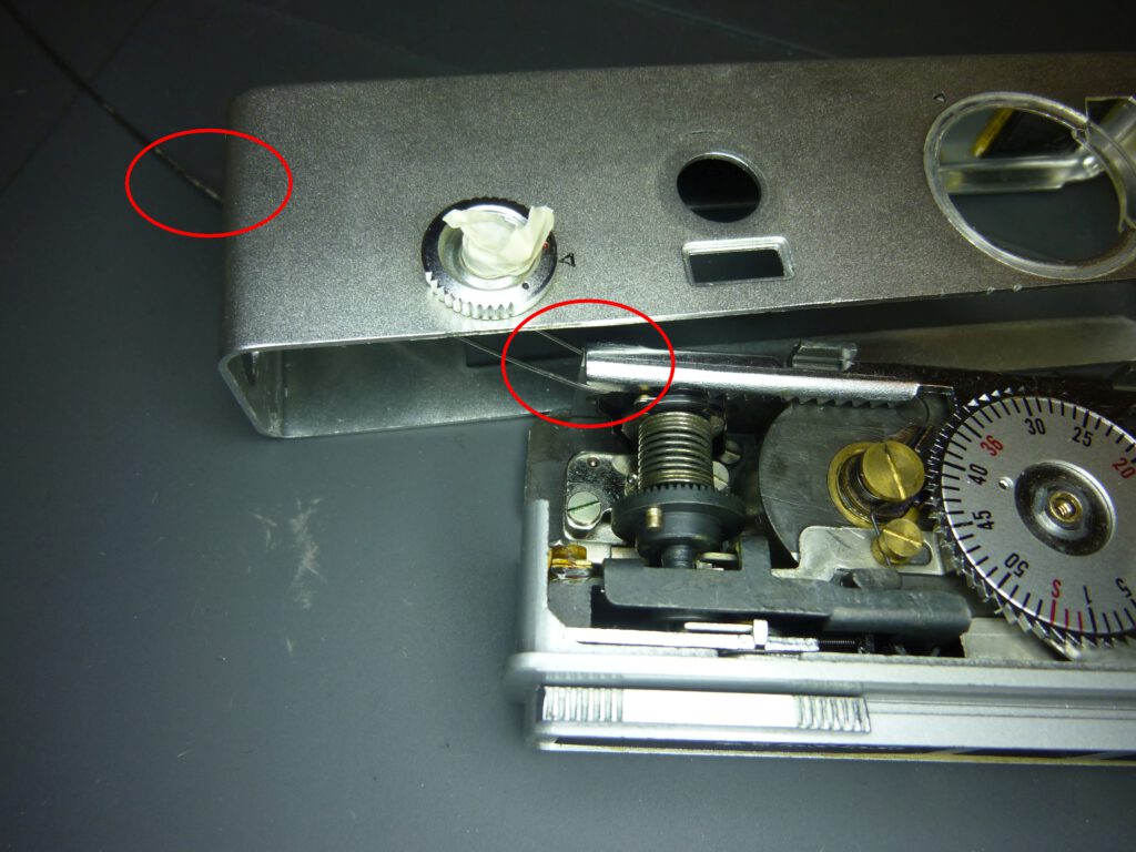
Now you can carefully pull the camera body out of the side of the housing. For me, it worked best when I first swung out the top part. This requires a little force, but be careful, if the housing gets stuck somewhere, you have to remove the cause first. It is recommended – as shown in the picture – to fix the shutter button in the pulled-out position with adhesive tape, otherwise it will get caught in the camera body when pulled out.
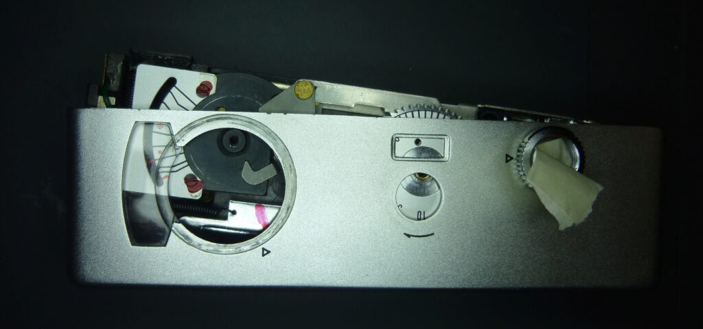
Finally, you can remove the front cover. This is necessary if you want to clean the yellow filter, the lens or the viewfinder. Or if you want to replace the selenium cell. The front corver is attached to the camera body at the ends with three slotted screws:
Now you can remove the cover. The camera then looks like this on the inside:

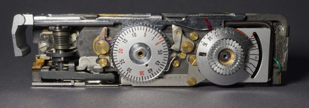

On the inside of the front cover you can see the yellow filter with the corresponding mechanism. To clean the filter, loosen the two screws and then remove the holder and filter. It is also advisable to clean the inside of the viewfinder glass.

Exposure control
To understand how the exposure control of the atoron works, we will take a systematic approach. We start by matching the needle of the light meter and look at the EV dial. We will analyze how the EV setting is passed on to the shutter. Then we go to the lens and learn the principle of how the blades open and close the lens. We then look at how this principle is realized by the atoron shutter. We start with the movements of the individual parts and then find out how this process is influenced by the EV dial.
EV-Dial
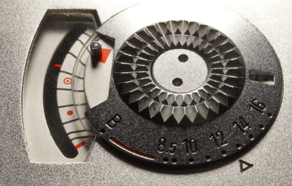
Exposure control is carried out on the atoron for speed and aperture together on the EV dial. So you set an exposure value and thus determine both. You can see which EV to set on the light meter. You therefore set the red dot on the EV dial to the red needle on the light meter.
To understand how the EV setting is passed to the shutter, let’s first look at the top of the camera body. A two-part cam disk 1 is mounted under the EV dial, which controls the exposure via two levers a and b:

Lever a is used to control speed and aperture in the EV range 8.5 to EV 16 (blue arrows). Lever b switches on the bulb mode “B” (red arrows). For further considerations, we only need to look at lever a and the area 1a of the cam. The actual exposure is controlled from this area. The desired exposure value is transported via lever a to part a at the top right and processed there. We will see later how this is done in another view of the camera from above.
Shutter
The shutter of the Yashica Atoron is a so-called “double guillotine”, in which two plates move in opposite directions over the lens and create an opening in the center. This type of shutter goes back to a patent by Sands from 1881.
Shutter blades
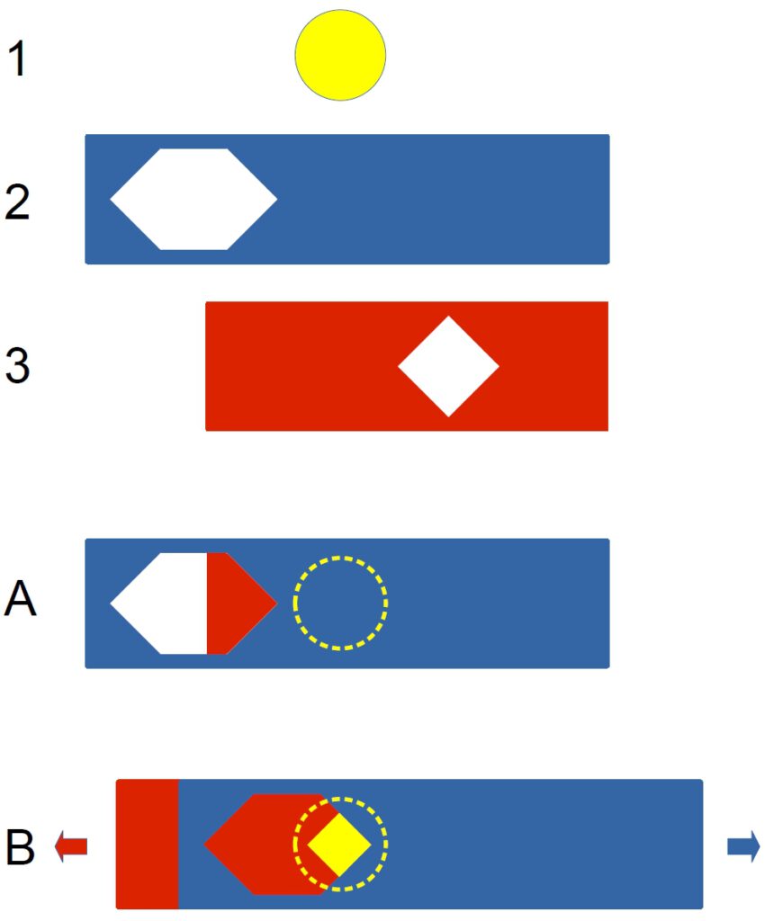
The shutter consists of two blades, each of which has a diamond-shaped window. When the lens is closed, both are on top of each other and therefore do not let any light through. When the shutter is released, one blade moves to the left and the other to the right, revealing a diamond-shaped opening in the lens.
The pictures on the left illustrate how the shutter of the atoron is constructed in principle.
The blades 2 and 3 are located between the elements of lens 1. When looking at the camera from the outside, blade 2 is located directly in front of blade 3.
Situation “A” shows the position of the blades when the shutter is closed. The lens is completely covered by both blades.
Situation “B”: When the shutter is released, the blades are pulled apart. Their triangular openings reveal a diamond-shaped part of the lens. As soon as the end position of the blades is reached, the movement is immediately reversed. Pulled by a spring, the blades return to their starting position at maximum speed. The lens is closed again. The shutter of the atoron is therefore by definition a central shutter, as it is located in the lens and opens from the center.
Shutter kinematics
This section deals with how the two blades are controlled as shown in theory in the “Shutter” section above. To do this, we look at the front with the lens (see photo below). The front plate of the camera and the shutter cover plate were removed for this purpose.
Blades 2 and 3 run through lens 1. On the right-hand side we can see that the ends of the blades are connected to a lever 5 (see also picture “End position” below). Lever 5 is pivoted by crank 6 when the shutter is released. As we will see later, crank 6 is driven by crown wheel 4. For now, however, we will concentrate on the movement of the blades caused by the rotation of crank 6. After completing the rotation, the return spring 7 pulls all parts back into the starting position.

Shutter control
The length of the blade stroke must be dependent on the selected exposure value. As we have seen above, the EV is transmitted from the cam disk to the shutter via the lever mechanism a:
The lever mechanism ends at the front as a seesaw a.
When turning the EV dial from 8.5 to 16, the lever a moves a little to the left. You can recognize the distance in the picture below by the two black markings. As long as the EV setting is not changed, lever a remains fixed in its position.
When the shutter is released, the crown wheel 4 rotates and a pin on the crown wheel (green circle) moves in the direction of the arrow towards the seesaw at the end of a. As soon as it hits the lower end of the seesaw, the upper end moves to the right in the direction of the arrow. This in turn rotates crank 6 and drives the blades as shown above. Meanwhile, the crown wheel continues to rotate at a constant speed and after a short time the pin releases the seesaw again. Spring 7 immediately pulls crank 6 back to its starting position.

The following video shows the complete process of driving the blades when setting EV 8.5 on the EV dial. For the simulation, the seesaw is driven by a pair of tweezers instead of the pin of the crown wheel:
The following video shows the complete process of driving the blades when setting EV 16 on the EV dial. Due to EV 16 note the new position of lever a, which is slightly further to the left (right marking line), and the changed starting position of crank 6. This has two effects: the pin of the crown wheel comes into contact with the seesaw for a shorter time and the blades only start to open later:
In reality, the rotary movement comes from the crown wheel 2 driven by the torsion spring, see illustration and video.
We have now familiarized ourselves with the complete kinematics of the atoron shutter. All that remains is to ensure that the crown wheel always rotates at the correct speed. This is the task of the escapement, which is described below.
Escapement
The escapement ultimately ensures that the camera precisely maintains the shutter speed assigned to the set exposure value i.e. that the blades always run at a constant, uniform speed.
How the atoron escapement works
The torsion spring drives the crown wheel 2. This turns the crank for moving the blades. To ensure that this movement is not arbitrarily fast, the crown wheel also drives the escapement 5, which forces a defined speed. The escapement prevents the crown wheel from rotating at maximum speed. The three-stage spur gear turns a rotating mass 4 in the fastest running stage and thus brakes the sprocket to a constant slower speed:
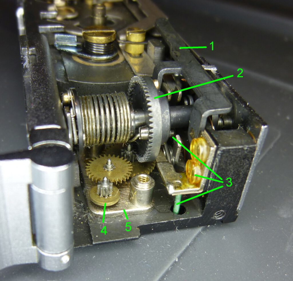
Here you can see in a video how the torsion spring is tensioned during the film transport.
The unique sound the Yashica atoron makes when the shutter is released sounds like woosh. It comes from the blades, levers and gears. See and hear for yourself:
The complete process takes about 1/4 second. Due to low speeds at the beginning and end, a noise is only audible for half of this time, i.e. 1/8 second.
Removing the escapement
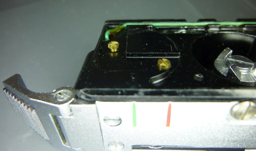
It is easy to remove the escapement completely in order to clean it. All you have to do is loosen two screws on the back.
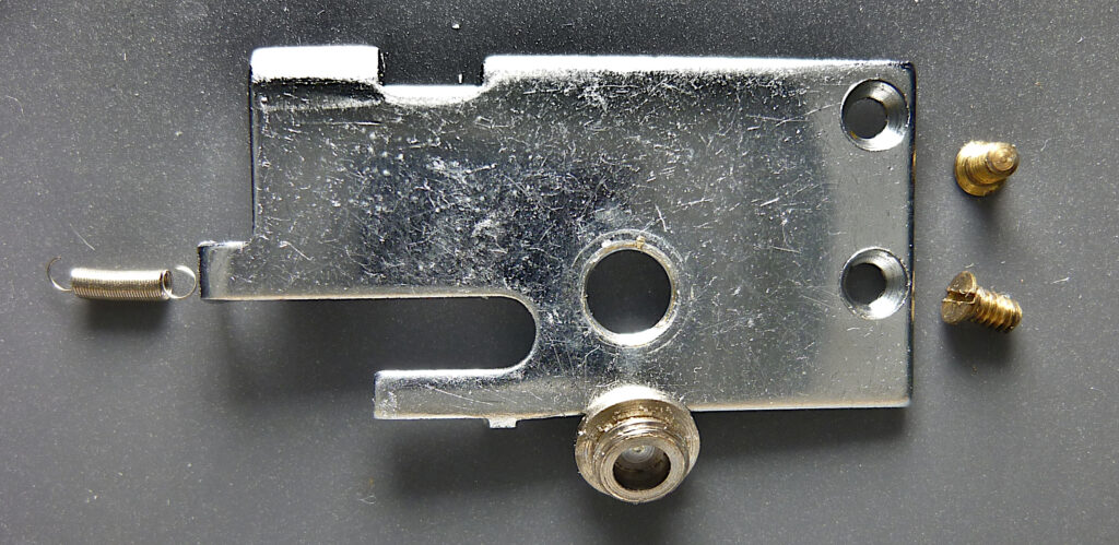
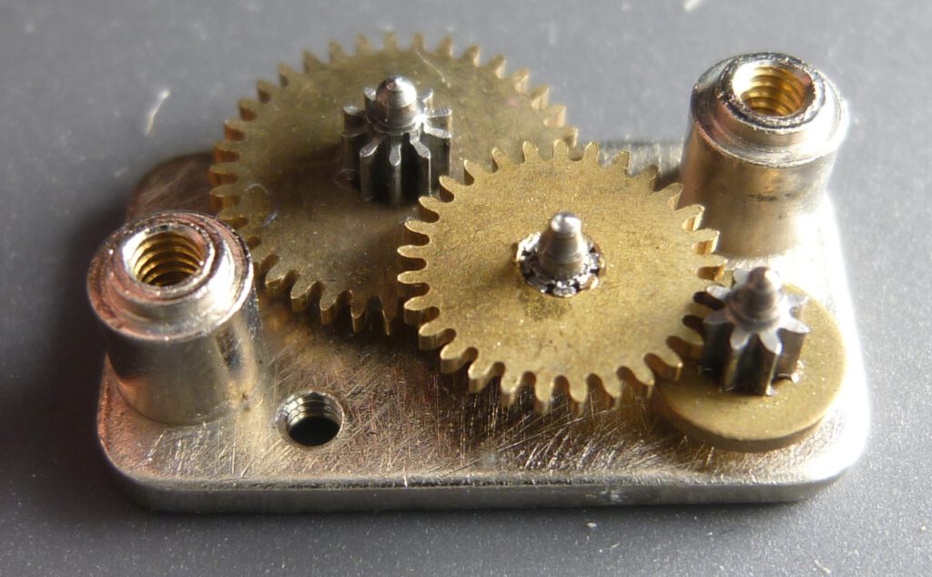
The escapement is then held in the hand as a unit.
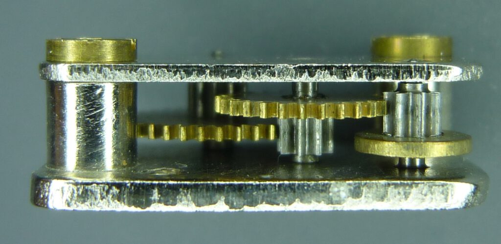
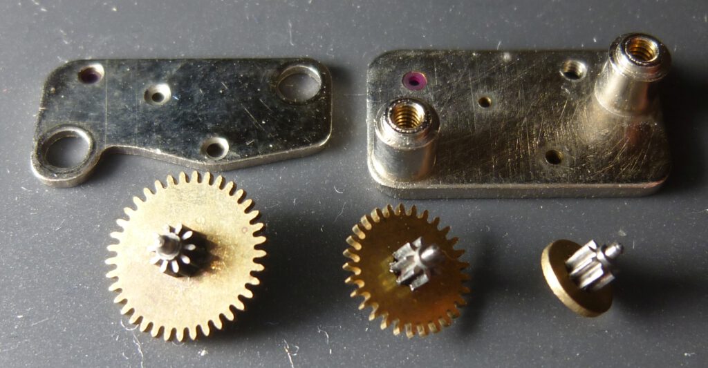
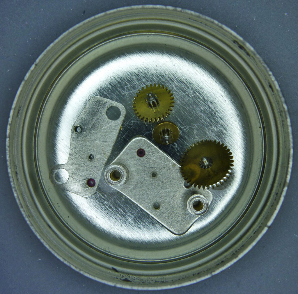
You can now remove the cover by loosening the two screws and disassemble the gearbox. This is certainly ideal for cleaning, but you can also clean the unit as a whole.
If you are wondering why the atoron can realize shutter speeds from 1/45 s to 1/250 s with such a simple escapement, you have to keep the following in mind. With this camera, the escapement must always run at the same constant speed regardless of the desired shutter speed. The escapement also always runs for exactly the same time. You can also hear this when you trigger the shutter at different speeds.
How is that possible? Well, as described above, the different exposure times are generated by a single rotation of the crown wheel at the same speed. To achieve the selected exposure time, only the slider crank connected to the crown wheel is adjusted.
This means that the escapement can have a very simple design. It only has to produce a defined speed for the force of the torsion spring on the crown wheel and the friction in the gearbox. The Yashica designers probably determined this simply by experimentation. In this way, they were even able to dispense with an anchor altogether.
Cleaning the escapement
Take the individual parts or the whole gearbox and put it in a can of lighter fluid for a few hours. Shake the can from time to time. Then remove the gearbox and leave to dry.
Now you should lubricate the three bearing points. I recommend NYOIL oil or Dr. Tillwich Precision Lubricant Grade 3-5. Apply small amounts with a special needle oiler (or a needle). Do not forget to oil the upper bearing points as well. This is best done when the top plate is refitted.
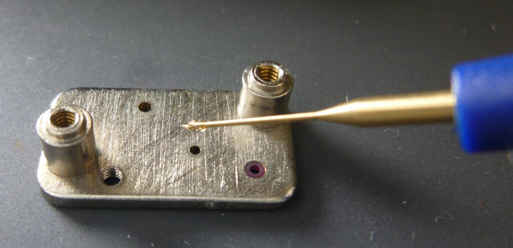
Note the ruby bearing on the front right. The smallest and fastest of the gears runs in it. Rubies are among the hardest natural materials. The use of a ruby bearing significantly reduces wear and friction, resulting in greater precision of the escapement. Attention, the teeth of the gear wheels must not be oiled, they should run dry.
Finally, put the unit back into the camera.
Replace selenium cell
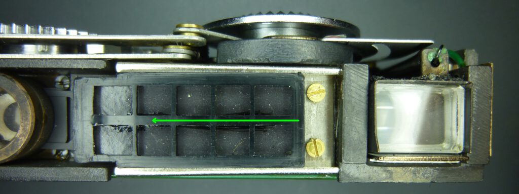
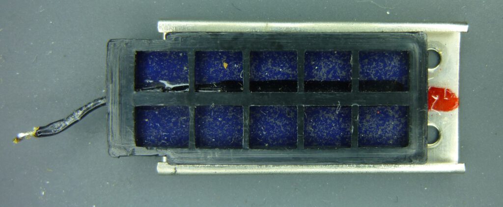
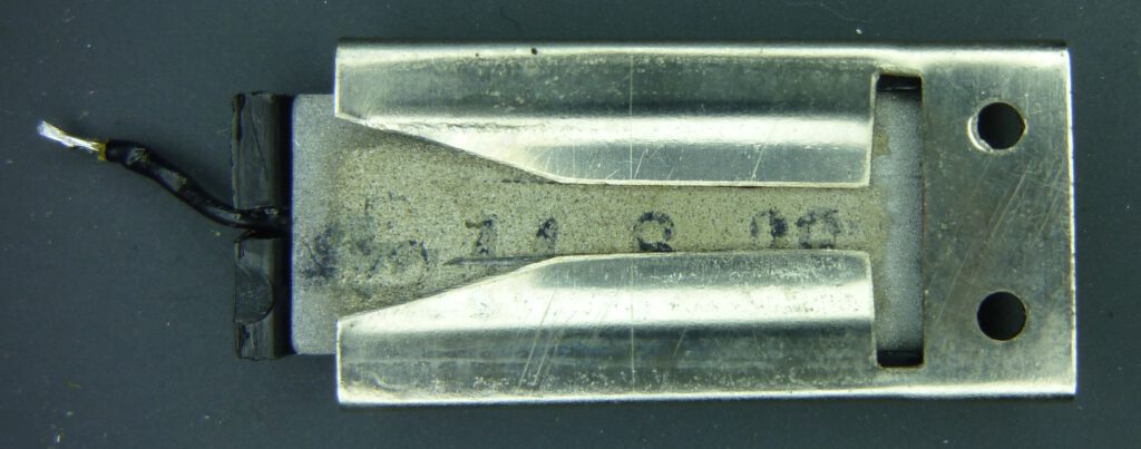
Replacing the selenium cell is easy if you have a spare cell. I took a working cell from another atoron. It was sold cheaply because the housing had a lot of damage. But the light meter still worked. To remove, slide the plastic housing of the selenium cell to the left until the two screws are visible.
Then loosen the screws and remove cell and holder.
Install original spare part
Cut the wire and solder the new cell to it.
Check whether the needle moves according to the incidence of light. Important: the cell must be screwed on, otherwise the electrical ground connection is missing.
Install up-to-date solar cell
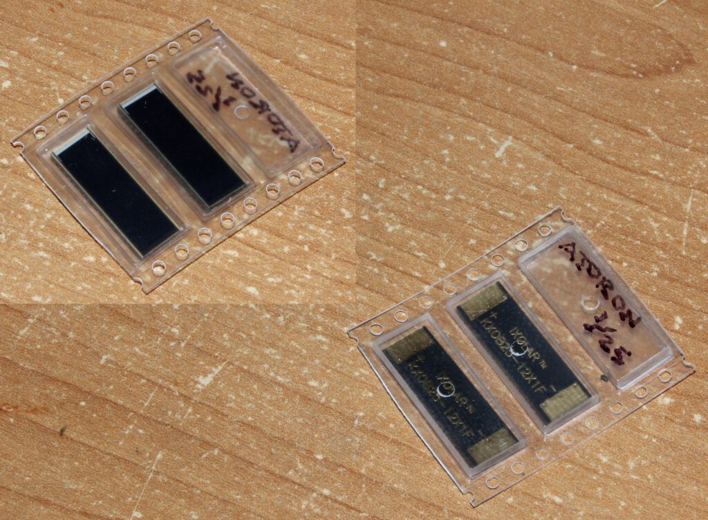
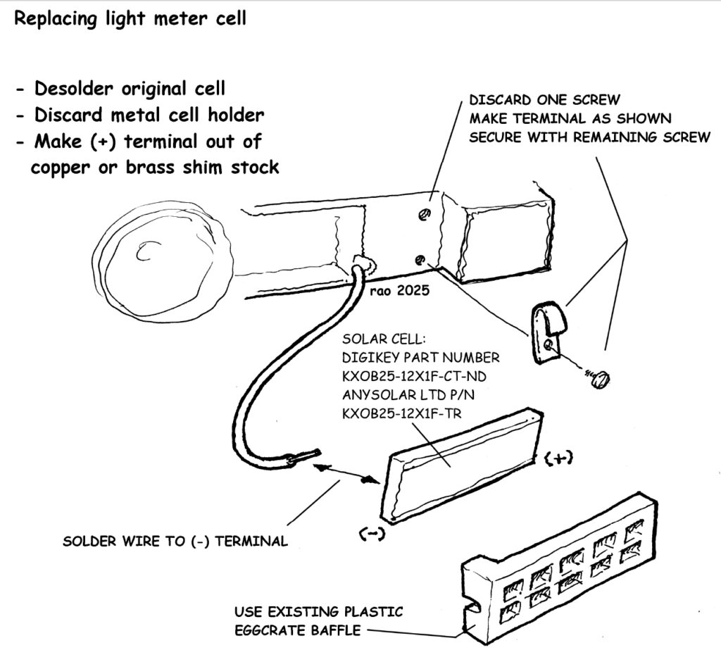
Rick Oleson shows here in detail how to replace the original selenium cell with an up-to-date solar cell (IXOLAR KXOB25-12X1F). He explains:
“I used the same light cell suggested in the article [photrio forum]. In addition to being slightly thicker than the original part as noted in the article, the new cell is also a few mm narrower and very slightly longer than the old part.I removed the original metal holder and filed away a small rib at one end of the plastic egg crate grill to make it fit. Because it’s narrower than the space around it, it is free to tilt slightly but no harm done – I could have made something to hold it horizontal but it didn’t seem important. Also, just letting it rest against the screw heads for an electrical connection did not seem adequate, so I removed one of the screws and made an electrical contact by bending a small strip of copper sheet into a U shape and securing it under the other screw – this makes a reliable connection at that end. The meter responds very well with its new cell, though I haven’t checked it for accuracy at this point.”
Film advance mechanism
Since the films for the atoron have no perforation, it must be ensured by other means that the distances between the negatives on the film strip are even. It must be taken into account that the film take-up spool has a smaller diameter for the first image than for the following images. This is because the wound film makes the diameter larger.
Let’s take a look at the solution first. If we set the frame counter to “1” and press the film advance lever, the take-up spool rotates by approx. 135°:

If we set the frame counter to “50” and press the film advance lever, the take-up reel rotates only by approx. 110°:

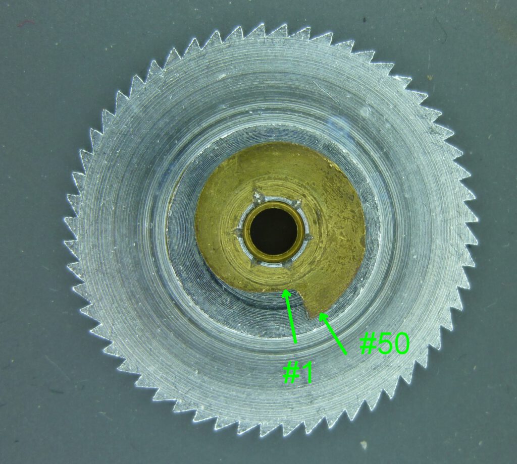
This compensates for the increasing diameter of the take-up spool. This solution is achieved with the atoron in a similar way to the Minox. The nose of the film feed lever is pressed against a cam disk located below the frame counter wheel:
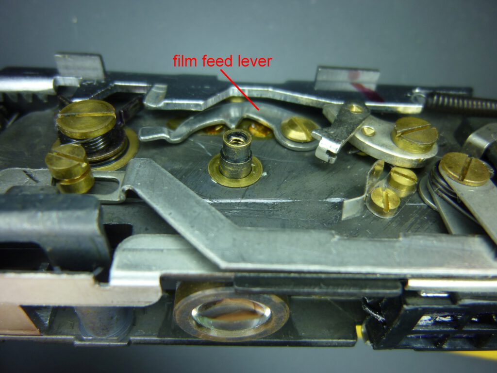
At photo #1 the nose of the film feed lever is on the smallest diameter of the cam disk, at photo #50 it is on the largest.
Depending on its position, the lever limits the stroke of the film advance lever and thus the angle of rotation of the take-up spool.
In the following video you can see what happens when you pull the film advance lever. In order to have a clear field of view, the frame counter disk was removed and its cam disks replaced by a washer. Note how the nose of the film feed lever, which adjusts the film advance, rests against the washer (cam disk). The brass screw in the center is the axle of the take up spool:
The further the nose is pushed outwards from the cam disk, the shorter the rotation of the take-up spool. On the right you can also see how the spring of the shutter is wound.
The film feeding mechanism works very precisely and evenly. On test films, I measured distances of 1.5 mm between the 1st to the 2nd negative and 2 mm between the 35th and the 36th negative.
Measure shutter speeds
Direct measurement of shutter speeds
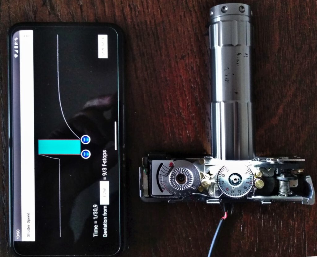
To measure the exposure times, I use the “Shutter Speed” app and the associated “Photo Plug” sensor. The Shutter Speed app uses this difference in brightness for the measurement. While the shutter is open, little light falls on the sensor. This time is measured and represents the shutter speed.
As the following picture shows, I place the sensor behind the lens in the open atoron. I place a flashlight in front of the lens. The app shows me the shutter speed after the shutter has been released.
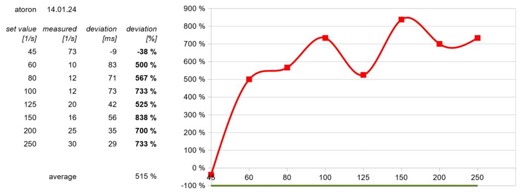
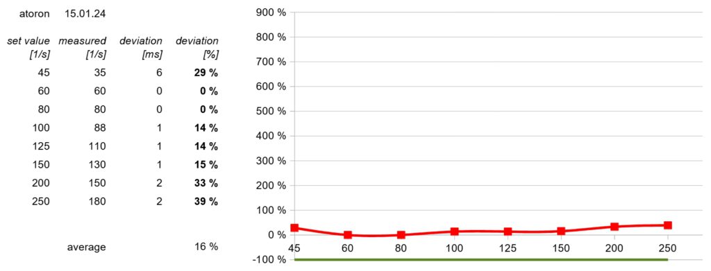
The two following evaluations show the measured shutter speeds and the percentage deviations before and after cleaning the escapement. While the times were 5 to 8 times too long before, they were as good as new again after cleaning and oiling.
Indirect measurement without opening the camera
Because we have now recognized how the atoron shutter works, we can take advantage of these three facts
- the atoron makes a characteristic sound when the shutter is released, which always has a duration of 1/8 second, no matter what shutter speed we set via the EV dial
- if the running time of the escapement is correct for one shutter speed, all shutter speeds are correct
- the lever mechanism and the blades are designed in such a way that they practically cannot wear out or stick together
The measurement is carried out using a smartphone and the free Shutter Speed app. To do this, press the smartphone with the microphone opening against the lens of the atoron and release the shutter. The app then shows the curve of the recorded noise:
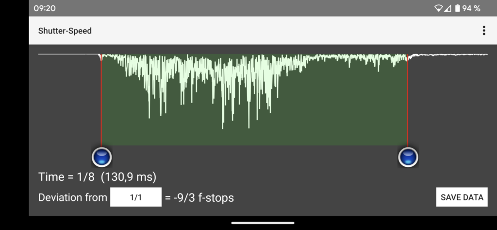
With the two blue buttons, we can measure the temporal extension, i.e. the duration of the signal, by placing them at the beginning or end of the signal. The beginning and end are not entirely clear, but the accuracy is sufficient.
You can see how the mechanics of the blades start to move and reach their highest volume. As soon as the blades have returned to their starting position, the noise level drops and you can only see the sound of the crown wheel and the escapement, which take longer to reach their starting position. We can see that the entire process takes about 1/8 of a second (130 milliseconds) and thus know that the camera’s shutter speeds are OK.
In the following picture we see the same curve again (top) but this time juxtaposed with a camera (bottom) whose shutter is so resinified that the escapement does not run to the end but stops before it does, namely after 96 milliseconds.
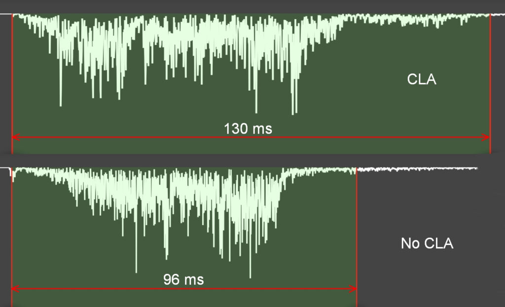
The escapement of this camera must therefore be cleaned and lubricated. The success should then be checked with a further measurement.
A significantly longer noise – I once measured 300 milliseconds – also indicates a shutter that needs maintenance. In such cases, the escapement does not stop but runs to the end, but too slowly.
It is sufficient to open the camera and remove only the escapement for cleaning. If you are not afraid of the effort, you can also grease (not oil) the sliding points of the lever mechanism under the top cover of the shutter.
Viewfinder
The Albada principle
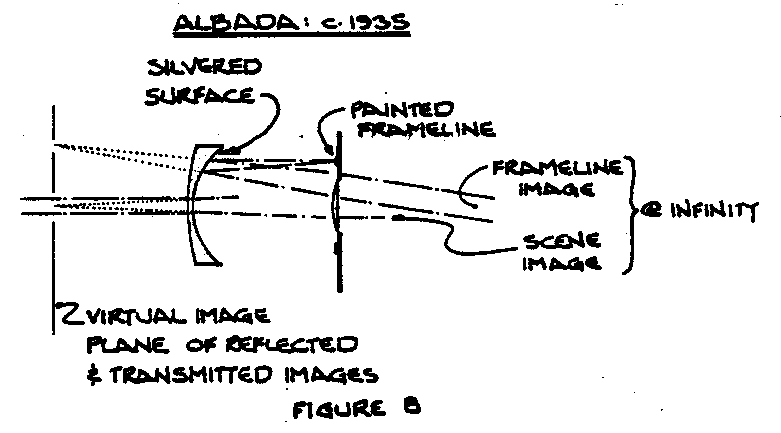
The atoron has a viewfinder based on the principle developed by Lieuwe van Albada. Rick Oleson describes it as follows:
“The Albada viewfinder, which appeared in 1935 in the Zeiss Contaflex 35mm TLR as a sports finder, introduced the concept of an optically projected image defining the edges of the field. This was accomplished by designing the front element of a Galilean viewfinder so that its rear surface could act as a semi-transparent concave mirror. With a white outline painted on the front surface of the eyepiece assembly, this concave mirror was configured so as to form a virtual image of the outline at the same apparent distance as the image of the scene which was formed by the refractive properties of the same element. With the eyepiece lens then brought to focus at this common image plane, the eye was presented with a reduced-size view of the scene, around which a white frame appeared to float in space. The three advantages of this system were that, first, the scene and the outline appeared in the same plane of focus, making more precise composition possible; second, the accuracy of framing was less sensitive to eye position; and third, the visible field extended beyond the composition area so that it was easier to track moving subjects.“
The atoron viewfinder
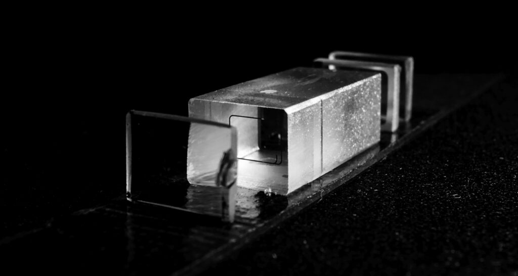
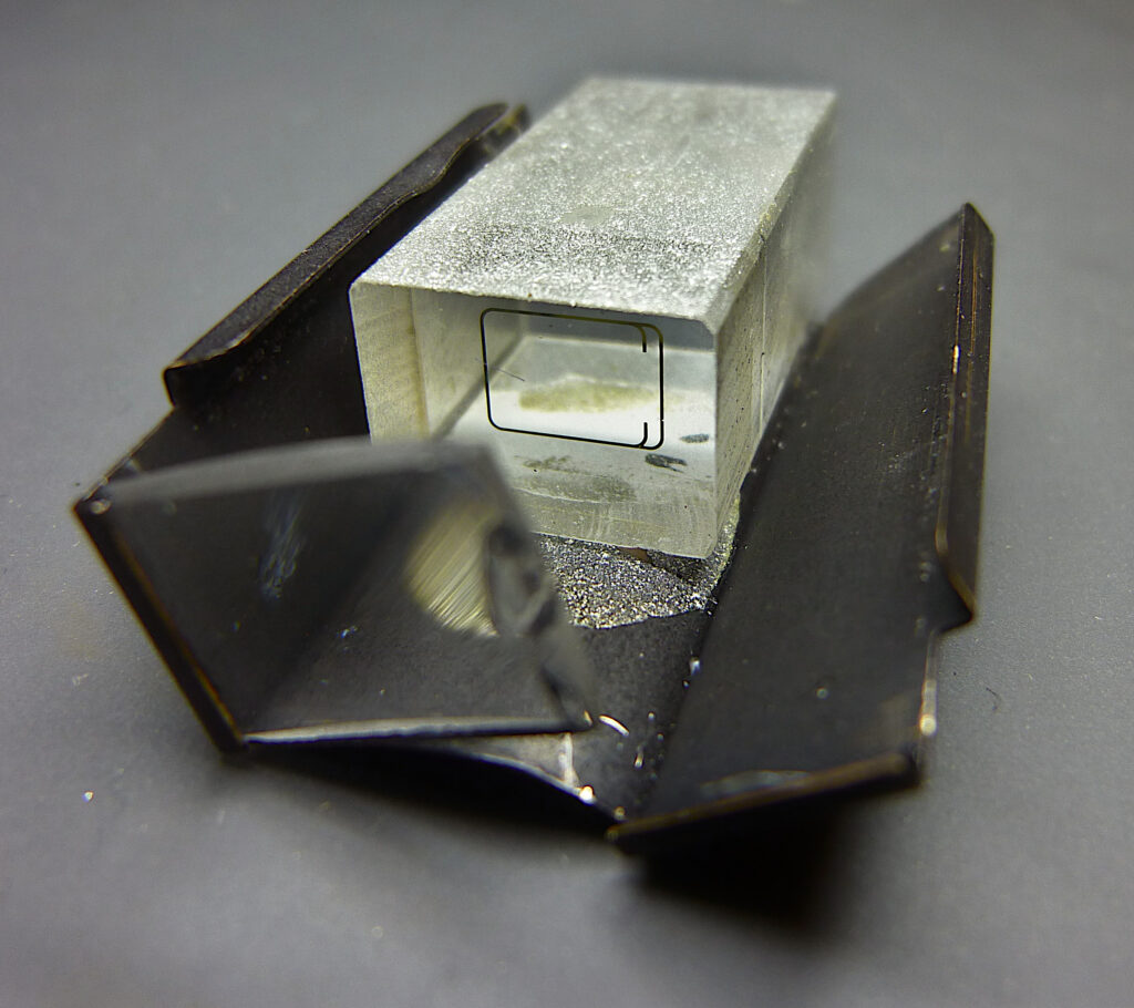
The viewfinder of the atoron consists of three lenses and a two-part glass block. It produces a slightly reduced image into which the frame and parallax compensation are reflected.

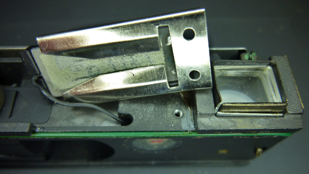
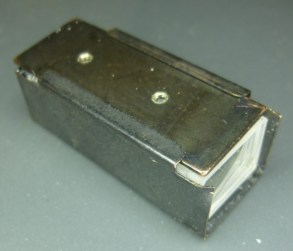
The picture above shows the removed optical elements of the viewfinder. They are held in the camera by a two-part sheet metal casing:
The eyepiece is about 1 to 2 mm away from the glass block. The other elements are directly adjacent to each other.
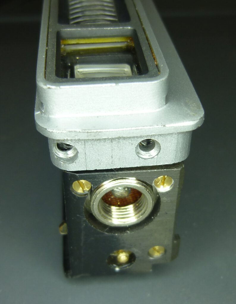
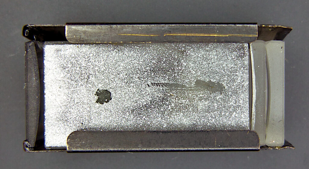
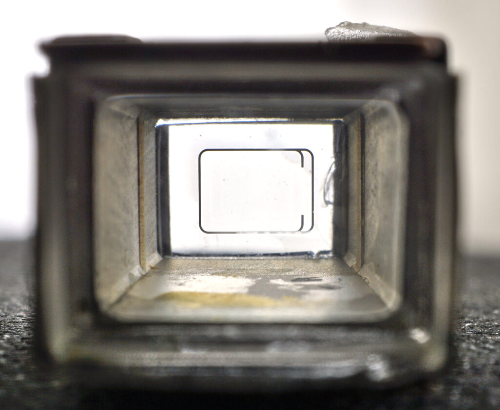
The housing consists of a plate that encloses the lenses on three sides and a top plate. The glass elements are glued into the plate. Two threaded holes in the top plate are used to attach the viewfinder to the back of the camera body. Here the dismantled viewfinder seen from behind (eyepiece):
The painted viewline is cemented between the two parts of the glass block. When using the camera, the frame is not black, as shown here, but its other, lighter side is mirrored by the silver-plated lens.
Cleaning the viewfinder
The viewfinder of the atoron is often cloudy. However, it can be easily cleaned and is then as good as new.
Open the camera and loosen the two brass screws on the back of the camera body that hold the viewfinder in place. The viewfinder can then be pulled out to the front. Then carefully bend the plate apart a little and pull the top plate out to the front. Now bend the plate far apart, see picture above. You can then remove the three lenses. If they are still firmly glued on, you can loosen the glue with hot air (110 °C). You can leave the glass body in the tray.
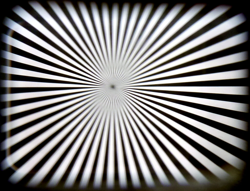
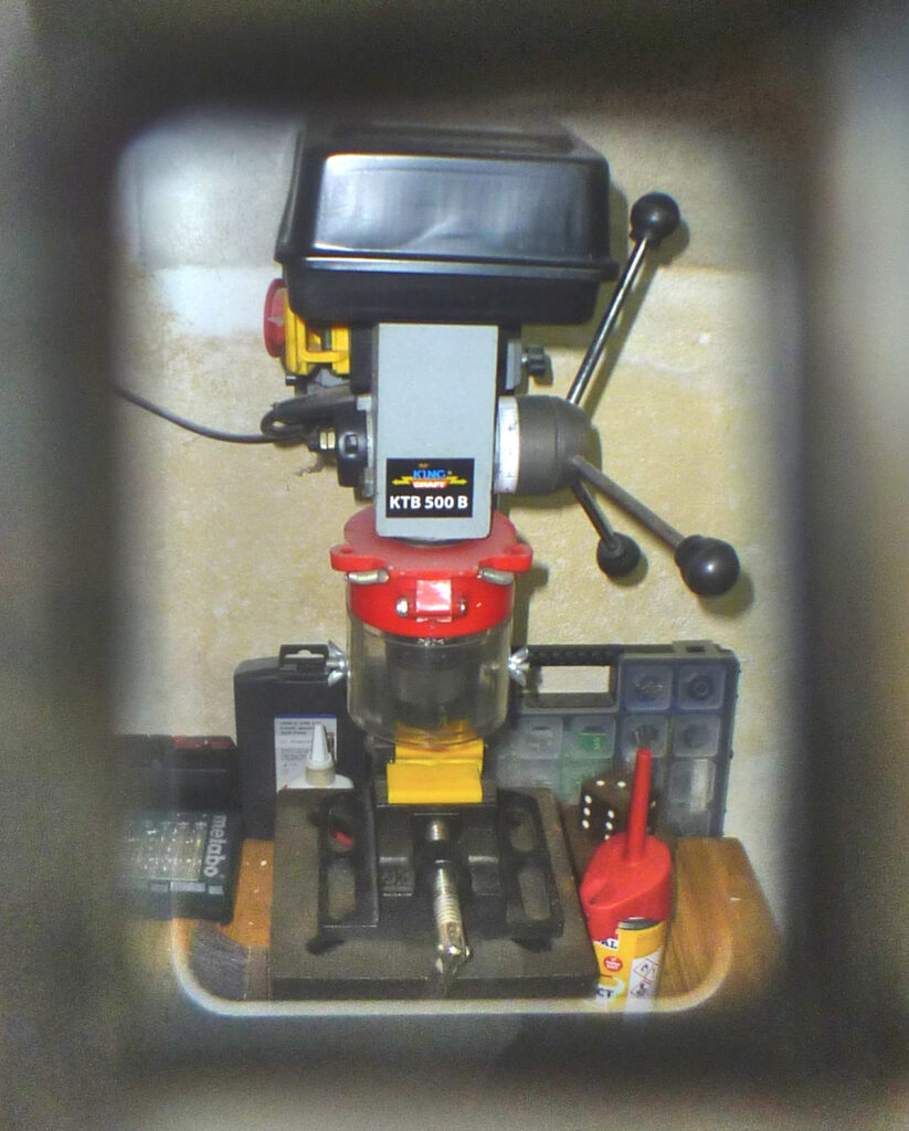
All glass surfaces can now be cleaned with a cotton bud or lint-free cloth with isopropyl alcohol. The surfaces should then be perfectly clean again. The following two pictures are taken through the cleaned viewfinder:
In reality the illuminated frame is much better to see and the field of vision is larger and sharper at the edges.
Then reassemble the viewfinder. In my experience, the distances between the lenses are not particularly critical. I simply placed the front lens and the mirrored lens at the front of the housing (on the right) and the glass block directly behind it. I placed the eyepiece lens at the very back of the housing (on the left). To fix the lenses in place, I first stuck thin double-sided adhesive tape to the bottom of the plate and the underside of the top plate.
Assemble the camera
In principle, the camera is assembled in the reverse order to opening the housing, see above. However, a few things should be noted when inserting the camera body into the housing.
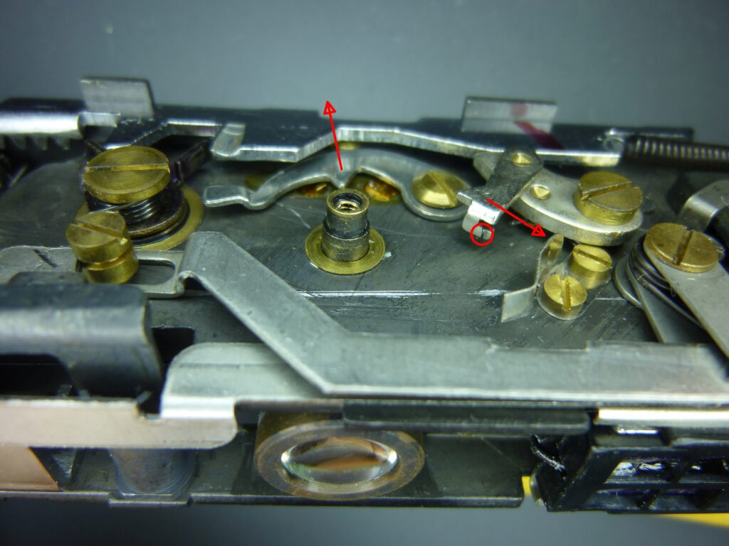
First, make sure that the frame counter wheel is in place. If you have removed it, you must pull the nose of the film feed lever and the lock lever in the direction of the arrow when inserting the wheel. Before doing so, make sure that the small spring (red circle) that presses the lever against the wheel is properly hooked in.
Second, the film advance lever must be fully inserted. But then you have the problem of not being able to screw the knob onto it later, as you can no longer reach the fixing point on the lever from the outside. That’s why I attach a wire to the lever beforehand, which I feed through the housing to the outside. This allows me to pull the film advance lever out of the housing later (up to the last snap-in point) and easily screw on the knob.
The third tip concerns the shutter release button. Fix the shutter button in the pulled-out position, otherwise it will get caught in the camera body when inserted. As you can see in the picture above, I fixed the button with adhesive tape so that it can’t slide down.
Summary
Overhauling the atoron is easy if you know the tricks. As the individual parts are not as sensitive as those of the Minox, you have a good chance of success.
