If it is difficult to find anything about the shutter of the post-war Minox models (A IIIs, B and BL), it is impossible to get any kind of explanation how the shutter of the Riga Minox works. After extensive internet research and unsuccessful inquiries through personal contacts, I had to accept that there really was nothing.
But giving up was not an option, I sat down and did a kind of reverse engineering of the Riga Minox. Here I would like to present the result of these many hours of analysis, thinking, calculations and visualization here. As always, my aim is to preserve and spread this knowledge about the Minox. I hope that other people will also be inspired by this ingenious camera design from 1936.
Page Contents
The principle of the shutter
First of all, we must be clear that the shutter of the Riga Minox is constructed completely differently than that of the subsequent models. If I was already impressed by the simplicity of the shutter construction, the Riga shutter completely astonished me. It is even more simply constructed and has fewer parts than, for example, the later Minox A IIIs. Nevertheless – and this is crucial – the accuracy and reliability of the Riga Minox is just as good. Before we delve deeper into this knowledge, let’s first look at how Walter Zapp constructed the shutter on his first model, the Riga Minox.
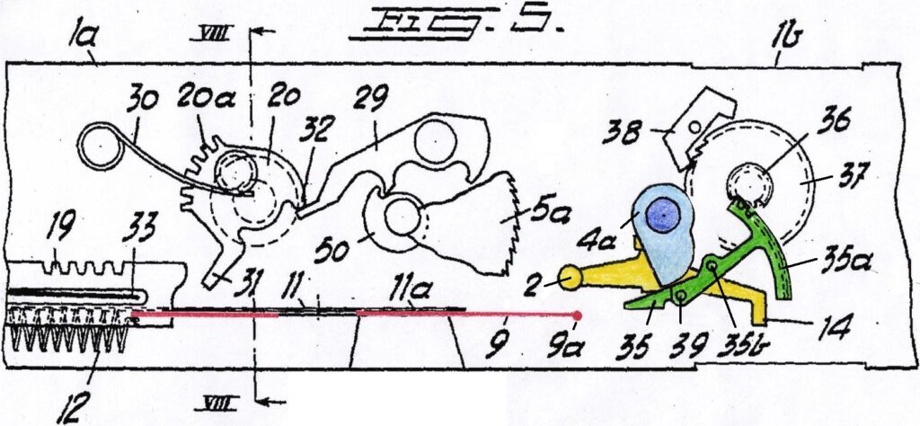
The following illustrations are based on the drawings that Walter Zapp created for the US patent specification in 1939 (US patent 2169548). He carried out the actual construction work in 1935-36. I colored the drawings to make the individual parts easier to recognize. I also extracted the moving parts from the drawings and put them together to create new images to illustrate the different states.
Basic principle
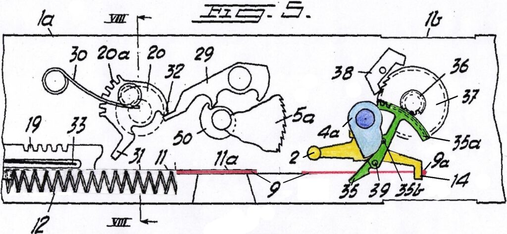
The Riga Minox has a guillotine camera shutter with one blade. This is the first big difference to all later Minox models, which work with two blades. When the shutter is cocked, the blade (9) is under tension of a spring 12 and is held in place by a catch lever 14. In this position the blade covers the lens (inner circle above 9):
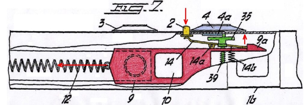
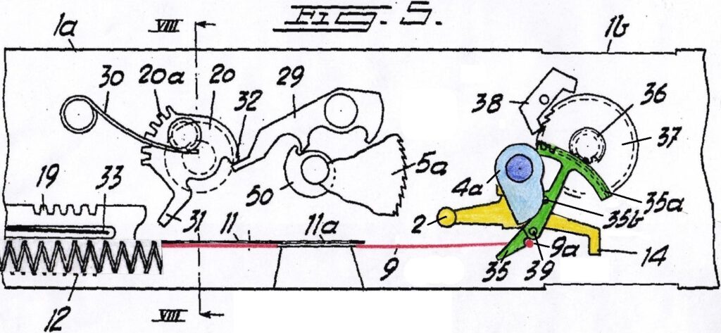
By pressing the trigger 2, the catch lever 14 releases the blade, which is then pulled to the left by the spring 12. The blade then hits the lever 35 and initially remains in this position. Now the window in the blade is directly in front of the lens and the lens is fully open:
As soon as the blade touches the lever 35, the escapement starts. This ensures that the lever releases the blade after the selected shutter speed has elapsed. The blade is now pulled all the way to the left into the end stop by the spring 12. The lens is then covered by the blade again:
The shutter process in detail
The shutter has two functions. Firstly, it opens the lens and otherwise shields it from incoming light. Secondly, it ensures that the opening takes place for exactly the selected period of time.
The first function is implemented by the blade and we have already learned about it above. The second function is a bit more complicated and we need to go into more detail. It is implemented as an assembly by the escapement. If you are interested in the basic functionality of an escapement, you can read about it here for the post-war Minox.
The Riga Minox escapement is significantly different and has a simpler structure than the later Minox.
Setting the exposure time
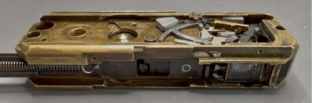
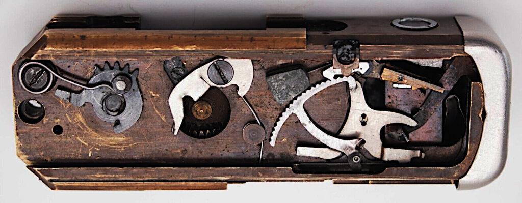
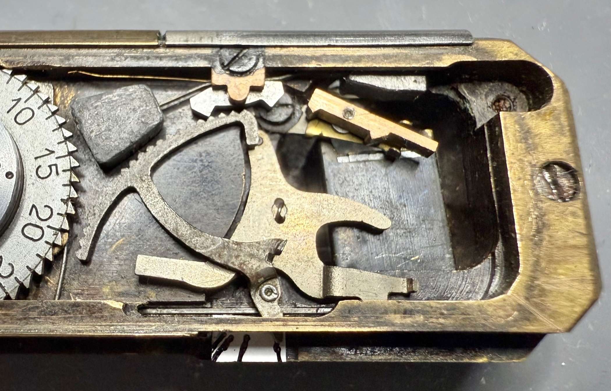
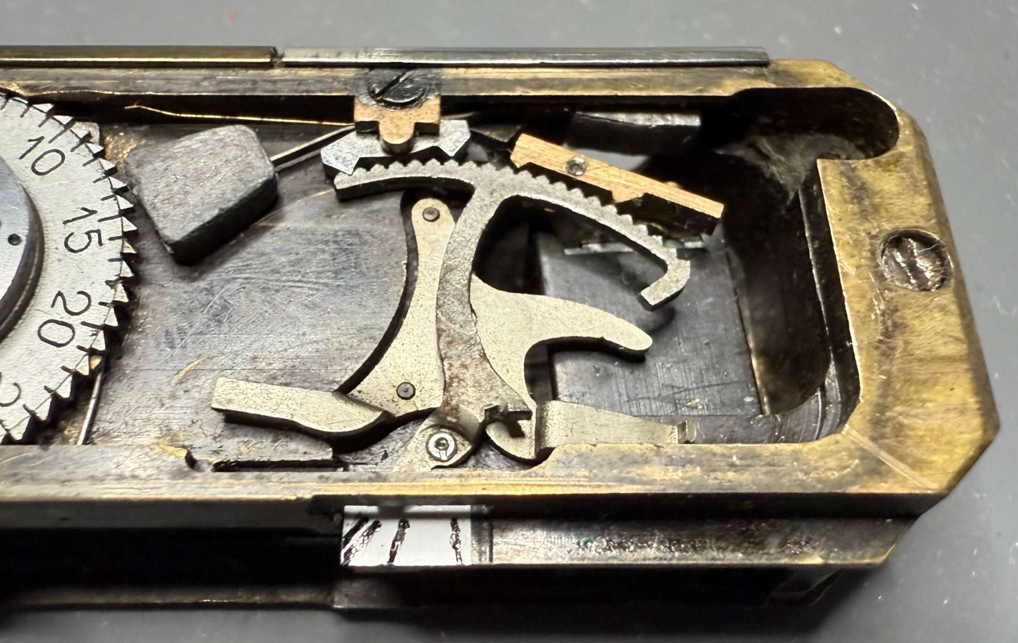
The following photo shows the escapement of an early Riga Minox in the right half:
The drawings from the patent specification below deviate from the photo, particularly in the case of anchor 38 and gear wheel 36. Nevertheless, they show perfectly how the escapement works.
Let’s start with setting the desired exposure time. The user turns the setting wheel 4 (see picture above), which is firmly connected to the cam disc 4a. The lever 35 is pressed onto this cam disc with its pin 35b. The pressing is done by the torsion spring 39a (see picture above).
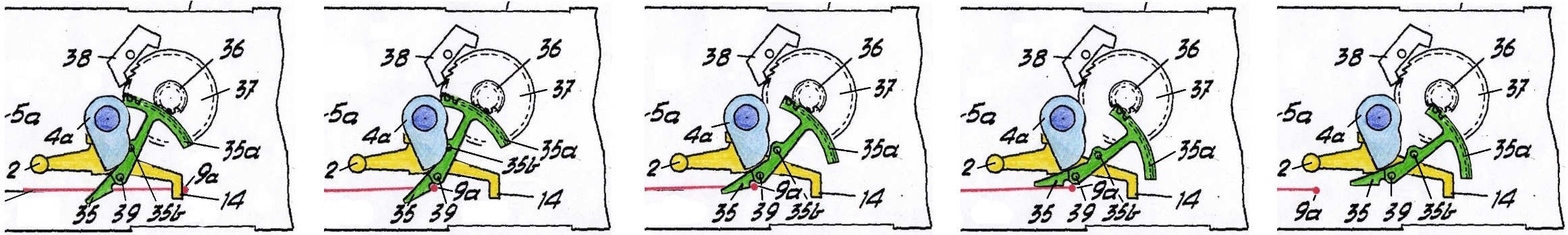
The following picture shows the cam disc 4a in the setting for the shortest exposure time:
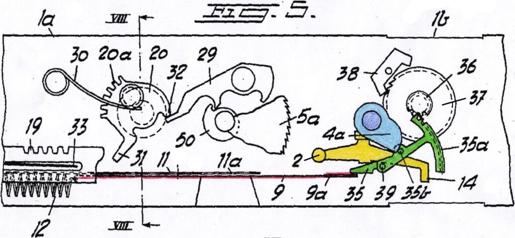
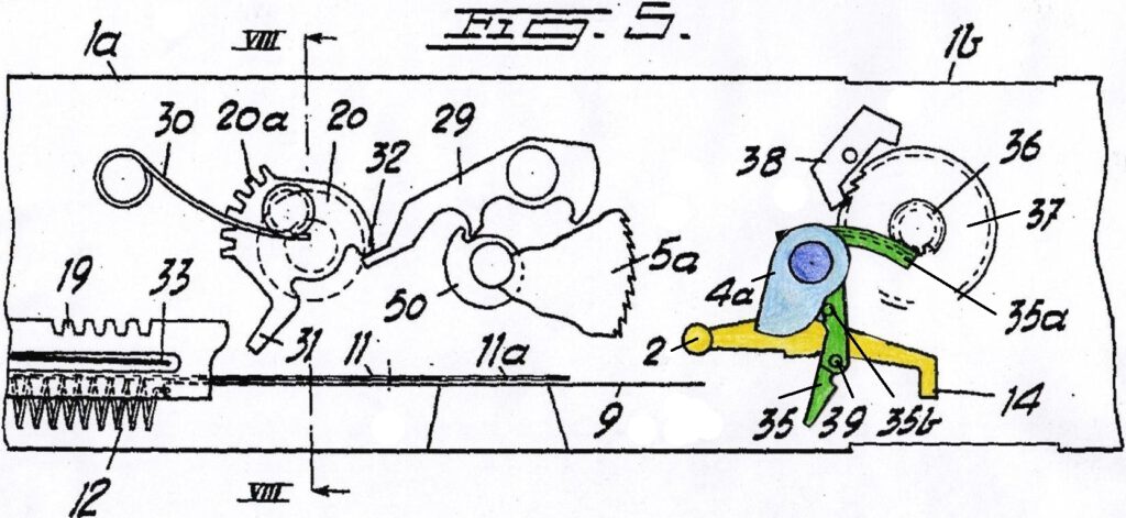
If the user now turns the setting wheel 4 to the longer exposure times, the cam disc 4a rotates clockwise. Again, the lever 35 presses against the cam disc and rotates counterclockwise to this position:
Triggering the shutter
By pressing the button 2, the right end of the lever 14 is pushed upwards and thus the hook 9a is released (lever bearing at point 14a):
Here the same situation in the top view:
The blade now begins to slide to the left due to the spring force. The blade moves until the hook 9a hits the lever 35 and thus sets it in a rotating movement:
Exposure
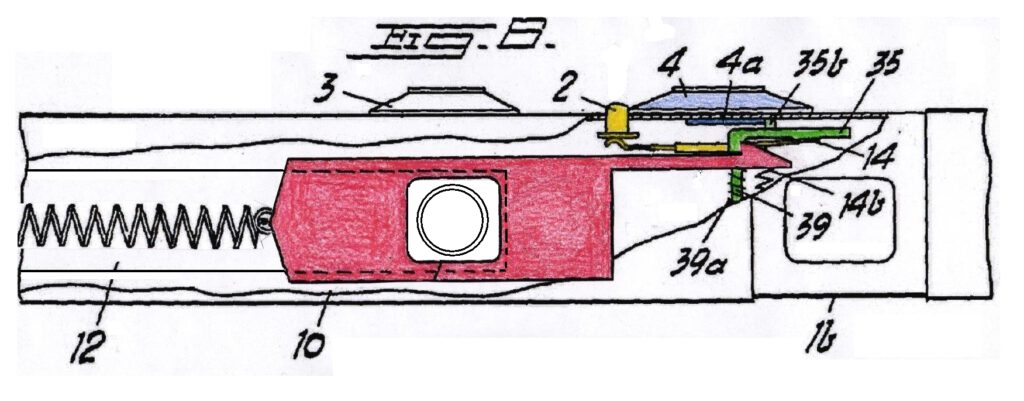
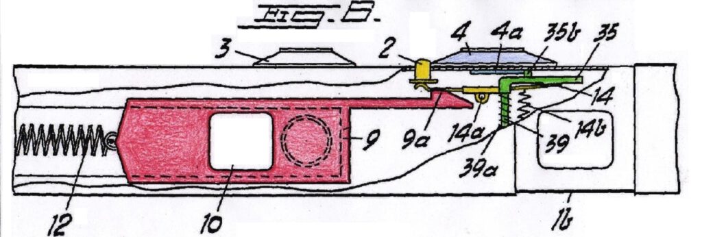
From this moment on the blade window is in front of the lense and the exposure begins. Here the same situation in the front view:
The task of the escapement is to hold the blade in this position until the exposure time is reached.
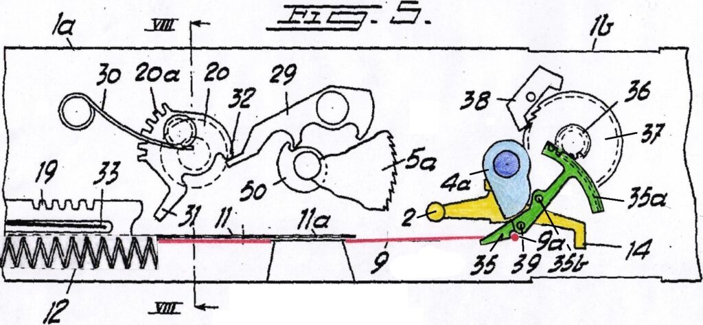
In the picture below you can see that the blade’s hook 9a, pulled to the left by the spring, rotates the lever 35 clockwise around its pivot point 39. The rotational movement is transferred to the gear (escape wheel) 37 via the sector gear. However, this gear is prevented from rotating freely by the anchor 38. Since the anchor oscillates back and forth around its axis of rotation, it only lets a single tooth of the wheel 37 pass each time. The oscillation frequency is always the same and so the escape wheel 36/37 always rotates at the same very constant speed. This principle is also used in mechanical clocks, see video here.
Closing the lense
The sector gear 35a rotates clockwise until the hook 9a is released from the lever 35:
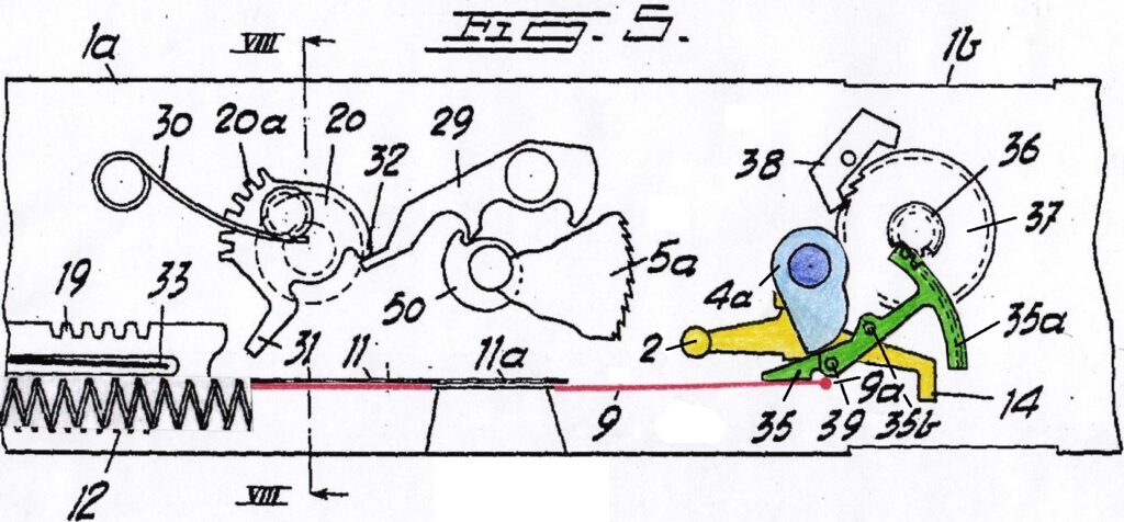
At this moment the blade 9 starts moving again and closes the lens:
Here the same situation in the front view:
Now the exposure process is complete and the camera must be cocked again.
The escapement
The second big difference to all later Minox models is the escapement design. It consists of just three components: the anchor 38, the escape wheel 36/37 and the sector gear 35a. The later escapements have an additional barrel with a drive spring inside. The Riga Minox uses the blade’s spring 12 to drive the escapement via the hook 9a and the lever 35. The escapement goes through the following phases:
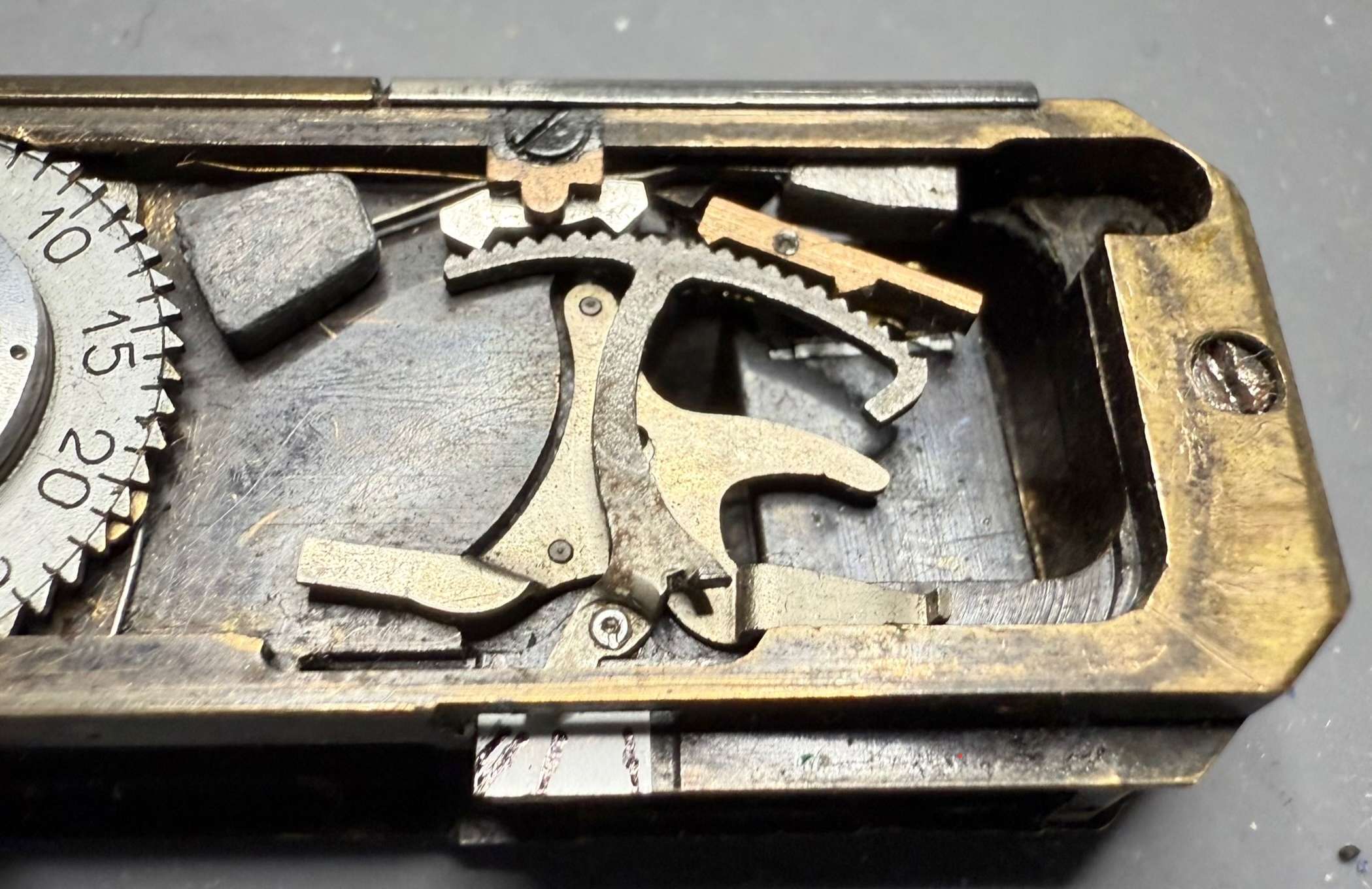
As can be seen in the following image, the actual design differs significantly from the patent description. Many thanks to Burkhard Fenner for providing me with the following explanation, photos and video. He also discovered why the Riga Minox actually has two anchors. He gained these insights into the Riga Minox, and much more, during his restoration of a VEF Minox Riga, which is described here for the first time.
Instead of anchor 38, there are actually two anchors. We will see why in a moment. Wheel 36/37 has been omitted. Instead, both anchors engage directly with gear segment 35a:

The left anchor (top centre, below the screw) has two lead weights attached to it with wires. To the right of it, we see the second, smaller, gold-coloured right anchor. This one has no weights.
The cam disc 4a of speed dial 4 moves the gear segment into the starting position. See the images below showing the starting positions for the long shutter speeds:

After the shutter is released, the shutter hook 9 pulls the gear segment clockwise from the starting position until the gear segment tongue reaches a horizontal position and the shutter then moves all the way to the left.
The two anchors were used because the gear segment only describes about a quarter circle and can therefore only travel a short distance, namely only about a quarter turn. However, a larger gear segment would not have been possible due to the minimal installation space.
For this reason, two anchors were chosen for one gear segment, with the left anchor, with its lead weights and therefore higher inertia, responsible for the long times – 1/2 to 1/20 s – and the right anchor for the short times from 1/50 to 1/500 s.
When the time is set to 1/1000 s, the lever 35 of the gear segment 35a is moved directly to the horizontal position so that the shutter travels without any delay. The escapement is not involved:
At 1/20 s, the left anchor is completely out of the way from 1/50 s onwards, and the escapement is then only controlled by the right armature.
The following video provides a unique inside view of the escapement in action at 1/2 s, captured in slow motion for enhanced clarity:
The oscillation frequency of the left anchor is generated by a spring-mass system consisting of two lead weights and a spring. This component is not shown in the drawings of the patent specification. However, it can be clearly seen in the video in the form of two gray masses that cause the anchor to oscillate. Due to its small mass and the absence of additional weights, the right anchor has a much faster oscillation frequency. It therefore causes the tooth segment to rotate correspondingly faster – at a precisely controlled speed.
The total rotation at shutter speeds from 1/2 to 1/20 s thus consists of an initially slow and then much faster rotational movement. The faster shutter speeds from 1/50 s on start immediately at the faster rotation. At 1/1000 s, the gear segment is locked at the right stop and the shutter then moves completely unbraked. Like everything else in this camera, it is a very sophisticated design…
This oscillation system (anchors – segment gear) has the same function as the balance wheel in a wristwatch. Since it always oscillates at the same frequency, it forms the time base for the escapement and thus for the shutter speed. If you want to know how the balance wheel in a wristwatch works, I recommend watching this animation.
Cocking the shutter
The shutter is cocked by pushing the camera together. Here you can see the starting position (after exposure, camera extended):
When pushing the camera together it must be prevented that light falls on the lens when the window 10 is pushed from the very left to the very right. To prevent this, there is a plate 11 (see top view) that has a window 11a (dotted outer circle in front view).
When the camera is closed this plate is moved to the right and closes the lens before the blade’s window slides past the lens. When the camera is extended the plate goes back to the left position bringing it’s window again in front of the lens:
The Riga Minox shutter in action
Following the detailed explanation of the Riga Minox shutter mechanism, this video by Burkhard Fenner provides a unique inside view of the shutter in action, captured in four-times slow motion for enhanced clarity. Watch as the intricate components work together seamlessly, bringing the previous descriptions to life:
Please note that, unlike the successor models, a bright circle appears in front of the lens after the shutter is released. Starting with the Minox A, it is exactly the opposite: the circle indicates that the shutter is cocked.
Conclusion
The shutter of the Riga Minox is a simple yet ingenious design. At the same time, it is robust and durable. After more than 80 years without maintenance, my Riga Minox still maintains the shutter speed values pretty good. I have measured the times electronically and listed them here.
Overall, the Riga Minox is excellently constructed and therefore it is not surprising that it takes amazingly good pictures and is practically as good as the Minox III.
Further articles on the VEF Minox Riga
- Restoration of a VEF Minox Riga: A unique description of a repair project with unique pictures and video of the inner workings of this camera.
- Minostigmat vs. Complan: A unique practical test that examines the quality of the two famous lenses.
- My VEF Minox Riga: The presentation of the camera and its design goals