While you can still find a little bit about how the shutter blades work on the internet, things look really bad with the Minox escapement mechanism. In addition, the escapement is complicated and hard to see inside the opened housing of the camera. In addition, the movement sequence, the kinematics, can only be guessed at when the mechanism is at a standstill.
I therefore created videos of what happens after the shutter is released with the camera housing open. I show these with the corresponding explanations on this page. To my knowledge, videos like this have not been published on the internet before, so stay tuned.
Page Contents
Integration in the Minox exposure system
The escapement is the third subsystem of the Minox exposure system.

It has the function of a stopwatch for the shutter blade control subsystem. It brakes the escapement lever for the set time. Only when the time has elapsed does it release the lever.
Why does the Minox need an escapement?
If you simply let go of the blade locking arm preloaded by a spring , it pulls the the locking pins down so quickly that the 1/1000 s occurs on its own. The Minox does not need any escapement for this shutter speed as explained here.
If you want the shutter to stay open longer, you have to control the movement of the blade locking arm differently in terms of speed.
To understand this description, I recommend reading the article about the shutter blade control subsystem if you haven’t already.
As we know, both locking pins are attached to the same blade locking arm:
How is the shutter mechanism driven? The blade locking arm with its two pins that hold the blades is pivoted in the middle. A strong spiral spring is located there, which rotates the arm clockwise after release.
In order to keep the shutter open for a specific time, the following process is necessary after it has been released:
- The blade locking arm is released by the trigger. A torsion spring at the pivot point of the arm sets it in rotation. The rotation is slowed down by the escapement.
- The arm starts moving and releases the opening blade via its short pin. Exposure begins.
- From this moment on, the arm continues to run for exactly the desired exposure time.
- Exactly after that the escapement disengages and the blade locking arm runs unbraked with maximum rotation to its end stop.
- Meanwhile the long pin releases the closing blade. Exposure ends.
The distance that the long pin still has to travel in phase 4 before it releases the closing blade does not matter because the pin is moved at maximum speed.
Rick Oleson worked intensively on the Minox shutter a long time ago and wrote one of the two standard articles about it. So I asked him to review my description of these 5 steps. Thankfully, he did this in detail and checked and confirmed the sequence also with the help of my slow motion video (see below).
The decisive factor is the speed at which the pins swing downwards in phase 3. This speed is always the same, regardless of the shutter speed selected and is regulated by the escapement. But what is the right speed?
The speed is easy to calculate if you consider that the longest possible shutter speed is 1/2 s. In this case the blade locking arm must be braked from the beginning of it’s movement. Since the two pins differ in length by 1.7 mm, the blade locking arm has to cover this distance in exactly 0.5 s. The required speed v of the blade locking arm during phase 3 can therefore be calculated:
v = 0.0017 m / 0.5 s = 0.034 m/s
The maximum speed can also be easily calculated. At a selected shutter speed of 1/1000 s it is maintained throughout the whole time of phase 3, i.e
v = 0.0017 m / 0.001 s = 1.7 m/s
Strictly speaking, the movement of the pins is not a straight-line (translatory) movement, but a circular one. This is because the blade lock arm is a lever that rotates around its attachment point. For our considerations here, this is negligible.
The task of the Minox escapement
The task of the escapement is to precisely control the angular speed of the blade locking arm. Depending on its starting position, which is specified by the speed dial, the lever, braked by the escapement, runs along the segment gear of the escapement until it releases the lever. This distance is precisely dimensioned so that the release occurs when the exposure time is reached. Then the lever accelerates to maximum speed. This causes pin 2 to immediately release the closing blade and the shutter closes.
The following video shows the release of the shutter and the subsequent movement of the escapement and locking pins with the camera open at a shutter speed of 1/2 s. In this video, the blades have been removed so that the pins can be seen more clearly. To see what the situation looks like with blades, click here. Note that at this slowest shutter speed, the lever is braked the entire time by the escapement. There is no acceleration to maximum speed here. Watch out for the rotation of the blade locking arm (far right) with the pins (bottom middle):
So the escapement mechanism has to ensure that the speed of the large segment gear arranged at the top is as uniform as possible. The designer chose an anchor escapement mechanism, like the one used in mechanical watches to realise this function.
How does an anchor escapement work?
History of the anchor escapement
Escapement mechanisms have been used for mechanical watches for a very long time. The oldest clock in the Western world with an anchor escapement dates back to the year 1670. Such a clock was also described in China as early as 1100. The Swiss anchor escapement still used today dates back to 1798. This further development made it possible to use it in portable watches and also in the Minox.
The regulation of a clock
The idea of the anchor escapement is to use a spring-mass system for torsional oscillation. The oscillation system provides a highly precise period of oscillation that drives a double lever (anchor) that controls the rotation of the escape wheel. The following video of the well known watch manufacturer Tissot shows such an escapement. Note the balance wheel with the torsion spring. These two parts create the time base, on whose accuracy the entire clock depends:
The Minox escapement
Components of the escapement
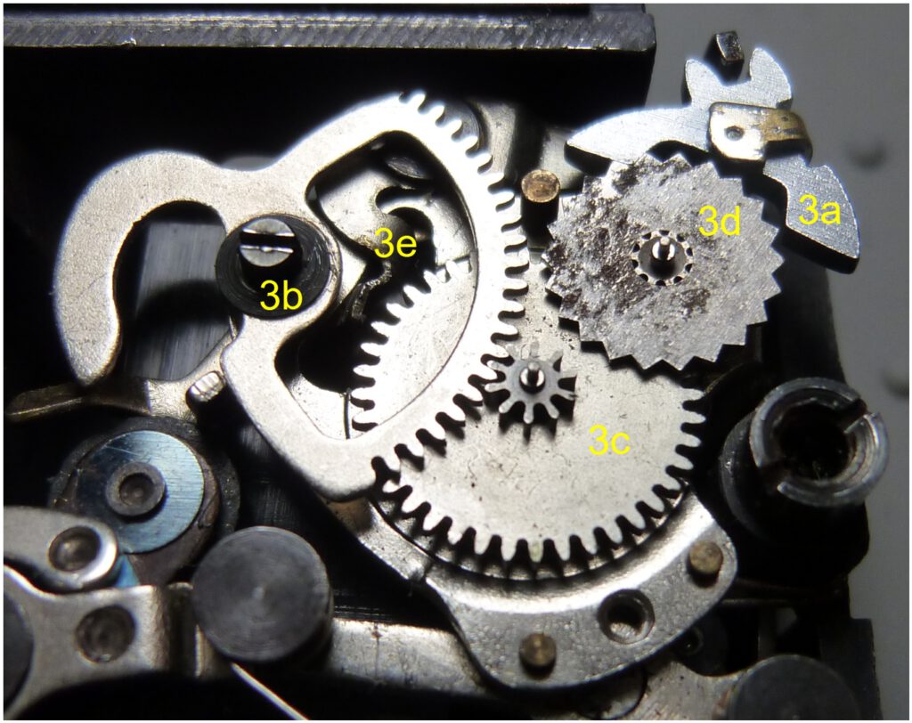
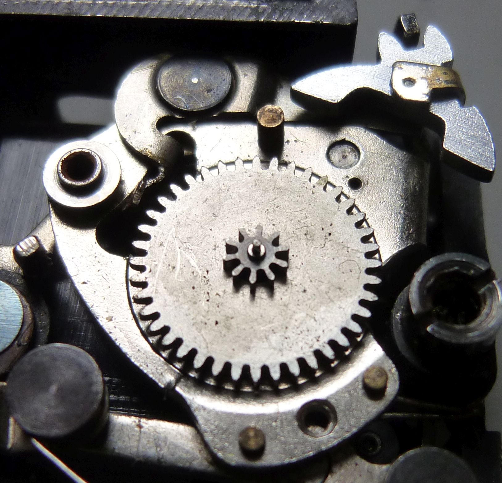
To understand how the Minox escapement works, we first need to get an overview of its components. The following image shows the main parts of the escapement:
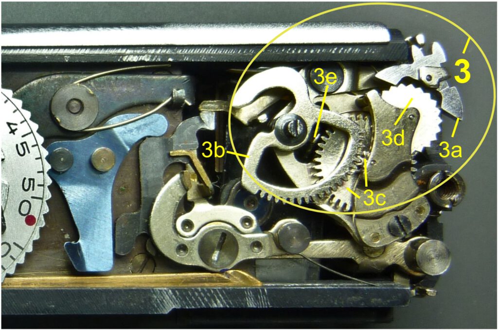
We begin with the anchor 3a. Unlike the clockwork presented in the video above, this anchor does not have a balance wheel with a balance spring. We will see later why this is not necessary here. The anchor controls the speed of escapement wheel 3d. This component consists of two gears mounted on a shaft: the actual escapement wheel and a pinion. This pinion meshes with the barrel wheel 3c and thus controls its speed. 3c also has a permanently attached pinion. This pinion meshes with the segment wheel 3d.
The escapement can therefore be regarded as a two-stage gear train, the fastest-running gear of which is the escapement wheel 3d. The gear train is driven by the segment wheel 3b. The whole speed is controlled by the anchor 3a.
Accuracy requirements
A clockwork places extremely high demands on the accuracy with which the gears and ultimately the clock hand are driven. This is necessary so that the clock displays correctly over a long period of time. A high-quality wristwatch is expected to have a barely perceptible time deviation of only +/- 6 seconds per day, which is +/- 0.007% (=6/24/3600*100).
In contrast, a deviation of +/- 25% is accepted for a mechanical camera with an exposure time of 1/2 second. Such tolerance would result in a time deviation of 6 hours per day in a watch!This means that a camera escapement can be 3600 times less accurate than a wristwatch. This low requirement was translated into a greatly simplified design at the Minox.
It means that the balance wheel and the balance spring could be completely dispensed with. Instead, the anchor is used as the oscillation element. There is also no torsion spring on the anchor. The balance spring is therefore replaced by the elastic deformation of the anchor arms when it strikes the teeth of the escapement wheel 3d in its end position. The pallets on the anchor, which minimize friction on the escape wheel in watches, were also omitted. The friction surfaces are even made quite roughly.
Size
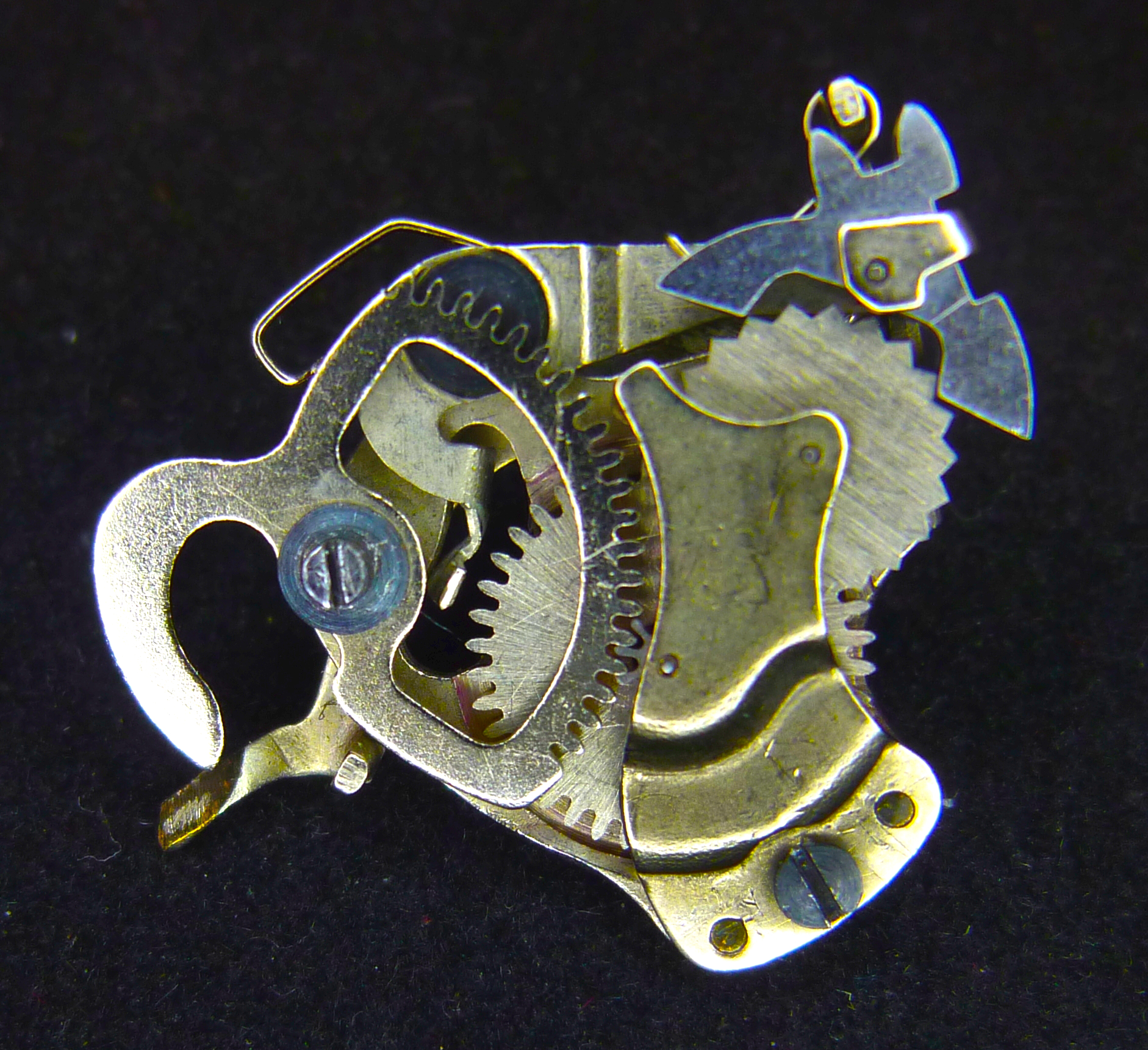
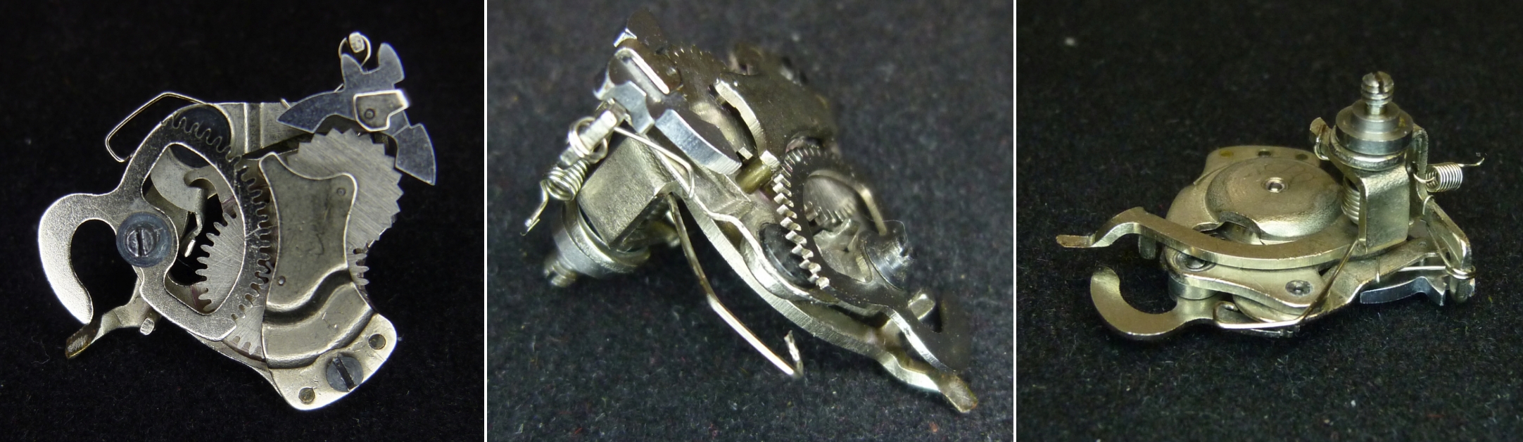
In order to accommodate the escapement in the Minox, the space must be used optimally. The removed escapement shows how the 3D design brings all functions and components together as closely as possible. Note also how tiny this assembly is: its largest dimension is just 20 mm and the whole thing weighs less than 3 grams. Here we see the Minox escapement asssembly removed from the body:
How the escapement works
The rotation of the blade locking arm (not visible) is controlled by the segment gear 3b. The torsion spring (not visible) installed in the barrel 3c drives during the cocking process the segment gear via the pinion attached to the top of the barrel. The escape wheel 3d is in engagement with the gear ring of the barrel via its pinion located below (not visible). The escape wheel is controlled by the anchor 3a and therefore cannot move freely. In this way, the anchor imposes a rotational speed on the entire gearbox that corresponds to the oscillation frequency of the anchor.
The following video shows the whole process in slow motion. Pay attention to the interaction of the anchor and escape wheel. At the bottom right you can also clearly see how the blade locking arm moves.
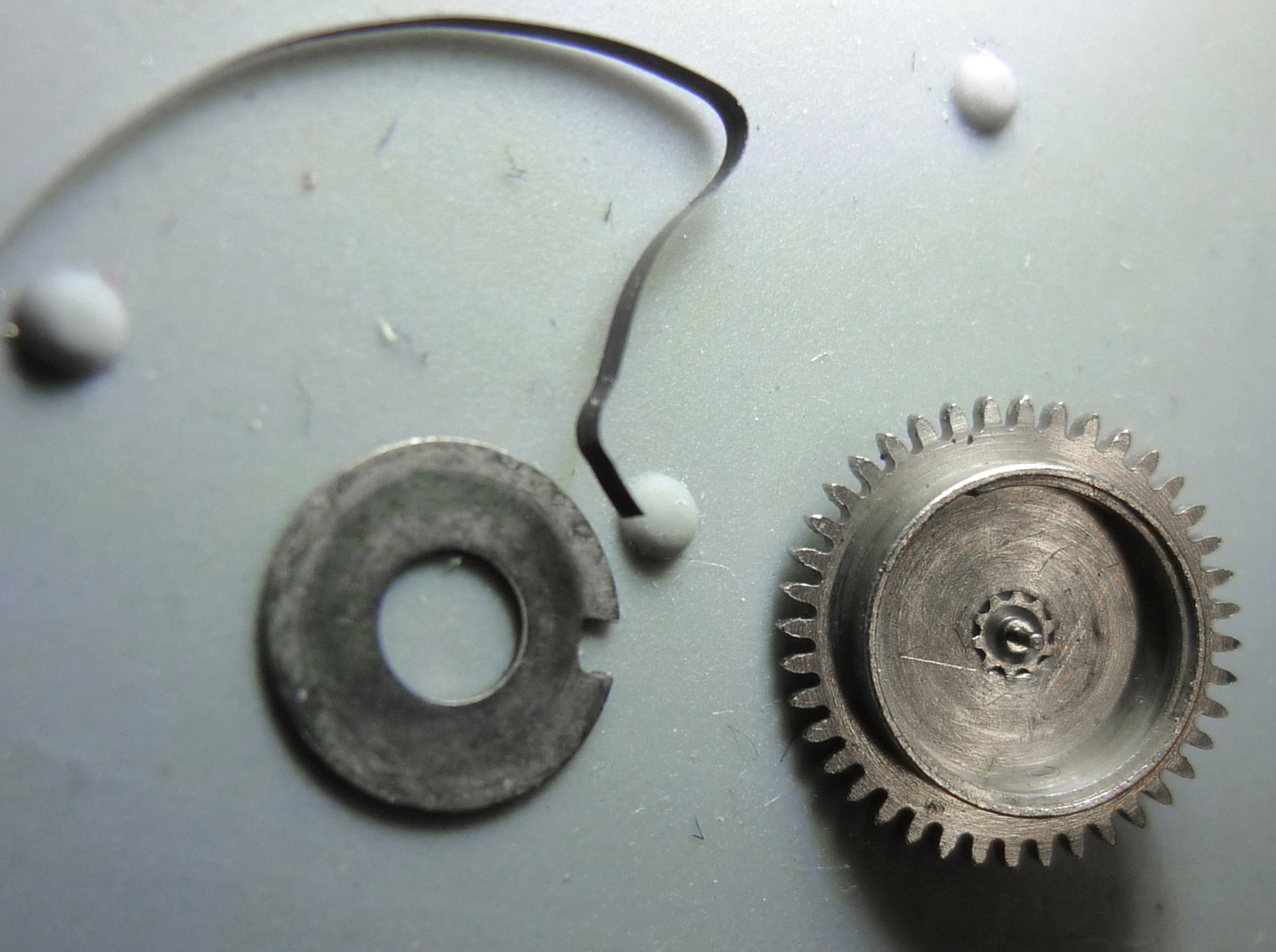
The individual parts of the escapement
The escapement essentially consists of 8 parts. There are 4 parts that are movable, namely the 3 gears and the anchor. There is also the gearbox cover, the anchor holder and two fastening screws. All parts are made of metal and are precisely manufactured. As you will see, the quality of the finishes is not comparable to that of watch movements. Pay attention to the dimensions and weights provided to get an idea of how tiny these pieces are!
Warning: If you want to continue using your Minox, do not disassemble the escapement! I sacrificed a Minox B for this because I wanted to take a closer look at every part. In my opinion it is not possible to reassemble the escapement mechanism without special tools. I tried but failed because of the drive spring in the barrel. There is no chance of winding up the hair-thin spring again or attaching it to the slot of the pin in the barrel mount. So do not loosen screws of segment wheel or barrel wheel under any circumstances!
Anchor
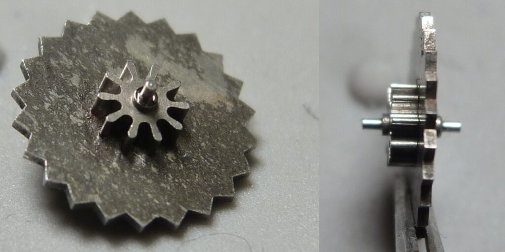
We’ll start with the most crucial and fastest moving part, the anchor:
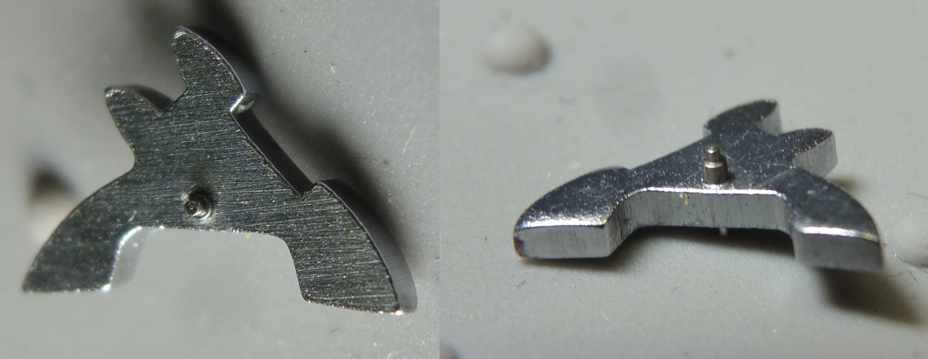
As you can clearly see in the picture on the right, the anchor has no pallets made of jewels. The pallets reduce wear and tear in watches due to their hardness. This is not necessary in a camera because of the comparatively very short running times. The surfaces that touch the escape wheel are even rough. Nevertheless, the accuracy of the oscillation for the shutter speeds is very good. So more precision is not required here. The bearing pins, on the other hand, are of excellent precision. The bearing pins run in the bearing points of a lever, which in turn is attached to the escapement housing in a rotatable, spring-loaded manner.
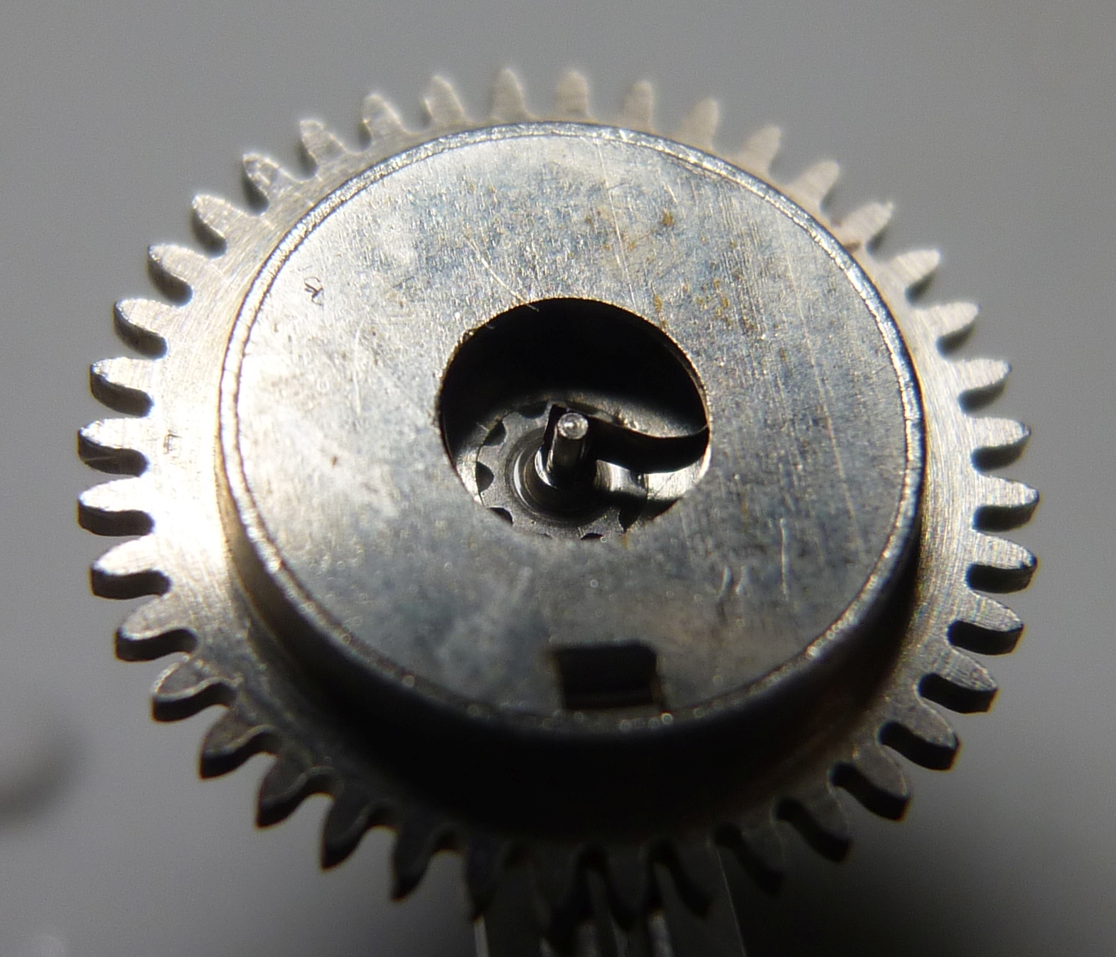
Escape wheel
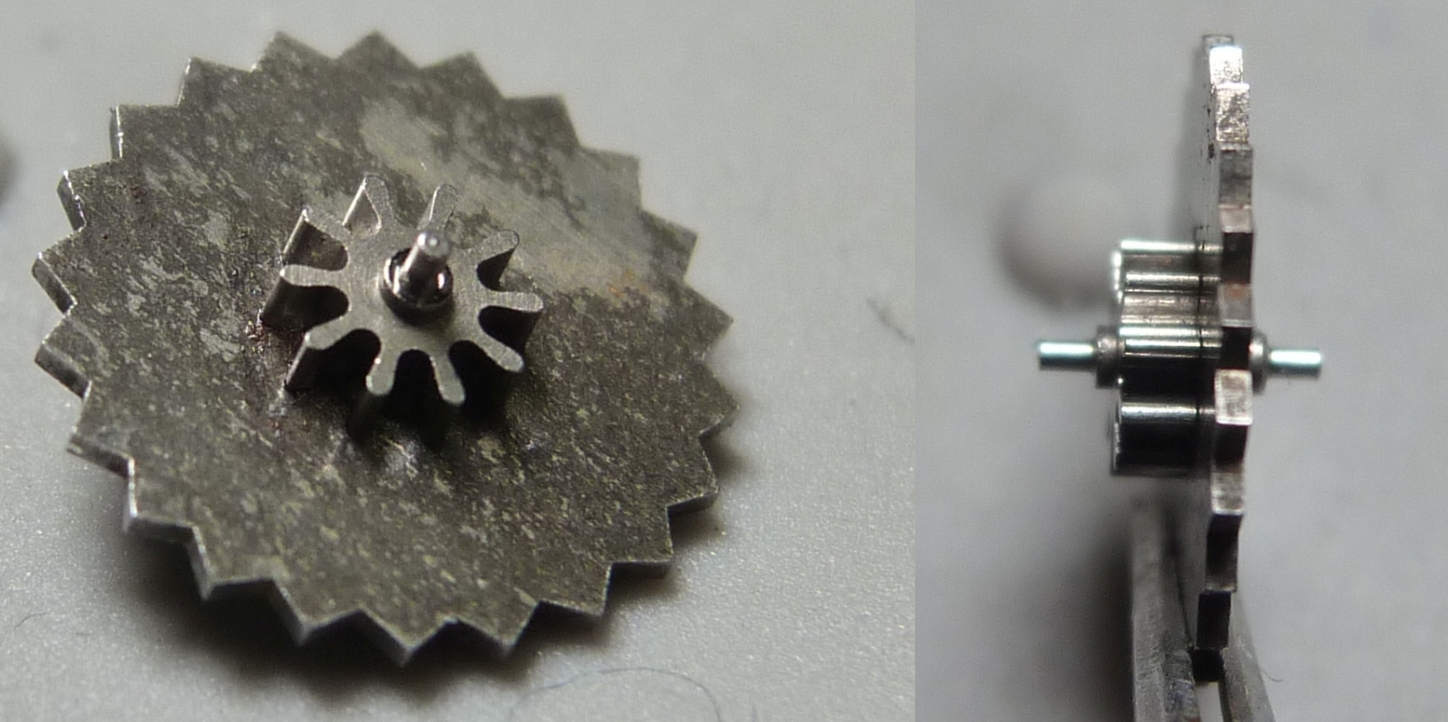
We now look at the escape wheel 3d as an equally important part. It consists of the actual serrated escapement wheel, the attached pinion and the bearing pins.
Note the shape of the teeth of the escape wheel, which is quite different from that of the other gears in the escapement. The teeth are shaped so that the anchor can engage optimally and control the movement. Note also the excellently manufactured teeth of the pinion. The wheel shown here comes from a spare parts box and is pretty corroded. Original parts installed are usually flawless.
The escape wheel’s pinion is in engagement with the barrel’s ring gear. This realizes the most important property of the escapement mechanism. It slows down the otherwise unhindered movement of the barrel. Let’ have a closer look at this module.
Barrel and spring
So far, we have only been able to see the barrel 3c from above and from the outside. However, it is a separate assembly consisting of five parts. Let’s take a closer look at them.
total weight 0.31 g
This assembly consists of a cavity that houses the drive spring, the spring itself and the cover. The spring is hair-thin. One end is attached to the outer edge of the barrel, the other end is connected to the arbor sitting on the escapement’s base plate. Let’s take a closer look:
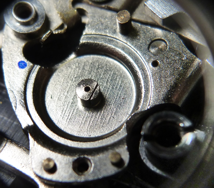
Above we see the bearing location of the barrel in the housing. The bore takes the shaft of the barrel pinion. Note the slot in the arbor. The spiral spring is attached to this slot.
Below, we see the spring itself:
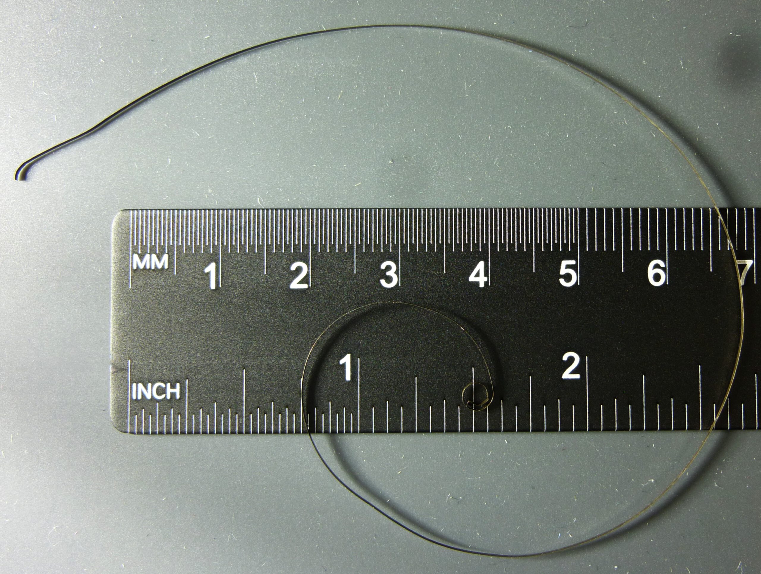
Barrel spring, 1 graduation line = 1 mm
Cross-section 0.5 mm x 0.03 mm, 220 mm long, weight 0.03 g
The spring is wound in a spiral in the barrel. It is wound when the shutter is operated by the segment gear. The internal spiral spring plays a crucial role in cocking the shutter. After the escapement has run down, the segment gear must be turned back to its original position during the cocking process. This is done by the spiral spring, see here.
You can hear this spring working when you set the shutter speed to 1/2 s and then cock the shutter. A soft buzzing sound can be heard, which is produced by anchor 3a and escapement wheel 3d, while the barrel moves backwards (counterclockwise).
It is important to note that the spring in the Minox escapement has a completely different function than the mainspring in a clockwork mechanism. The mainspring in a clockwork mechanism drives the entire clock and ultimately ensures that the hands move. The spring in our escapement, on the other hand, has no function at all while the shutter process is running. It does its work beforehand when setting the exposure time.
The barrel’s pinion can be seen in the next picture, which shows the barrel partly assembled.
How the segment gear controls the escapement lever
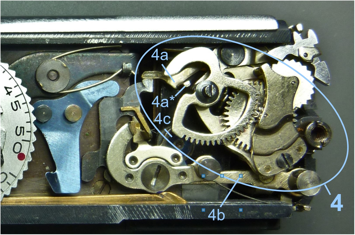
Now let’s move on to the segment wheel, which controls the rotation speed of the escapement lever 4a* and thus the blade locking arm 4b.
The segment gear is attached to the escapement body with a special screw. The screw also serves as an axis on which the segment wheel can rotate freely. The screw has a pin-shaped head, which is used to set the exposure time. Details can be found here.
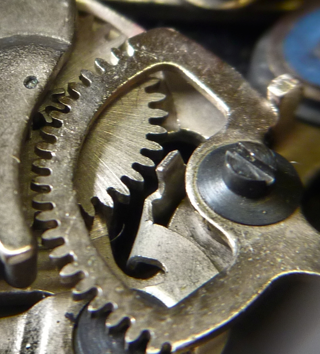
You can clearly see here how the segment wheel engages to the pinion of the barrel. In this way, the barrel wheel is driven by the segment wheel. However, the barrel wheel cannot rotate faster than the speed set by the anchor. This speed of the segment wheel in turn controls the escapement lever 4a via its flank:
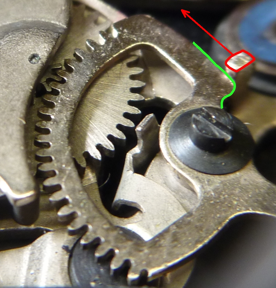
The photo above shows the path (green) of the escapement lever 4a (red) moving to the end position at maximum speed after being released by the cam of the segment gear.
Now that we have looked at all the components in detail and understood how they interact, we should take another look at the movement of all the parts in their dynamics. In the following video, pay particular attention to pin 4a* as it presses on the cam disc of segment wheel 3b and slides along it until it is released and the exposure ends.
Summary
We learned why the mechanical Minox needs an escapement. To do this, we looked at escapement mechanisms in general, as they are used in mechanical watches. Due to the comparatively very short running times of the escapement in the Minox, the design could be greatly simplified. The individual parts were introduced and their purpose was explained. A unique slow motion video shows for the first time how the escapement works when the Minox is open. This makes the interaction of all parts clear.
Go to the next article How the Minox blade control works
Back to the article The minox exposure system