What does a VEF Minox Riga look like on the inside? How do you repair it? What individual parts does it consist of?
This restoration account presents globally unique insights, images and videos of the VEF Minox Riga’s intricate mechanisms, addressing these details for the very first time ever.
Unfortunately, as of 2025, no information was available online or in book form about the VEF Minox Riga repair or its inner workings. And these differ significantly from all subsequent models! So no photos, no descriptions, no repair manuals.
Then a few weeks ago, Burkhard Fenner told me that he had managed to completely restore a VEF Minox Riga, of which he only had individual parts and I was thrilled to hear this. I immediately asked him to present his project here, and he agreed. Read what he reports.
All images in this article can be enlarged by clicking on them.
Page Contents
VEF Minox Riga – Brought back to life
by Burkhard Fenner
For some time now, I’ve been fascinated by old analog cameras, but it wasn’t until recently that I came across a Minox. While delving into the subject, I naturally stumbled upon the history of this camera and its inventor, Walter Zapp. When I read about the camera’s origins and development in Latvia and explored the technology of the first series in detail, I was hooked. I was so captivated by this delicate yet robust VEF Minox Riga that I absolutely had to hold one in my hands.
After tracking available cameras online for quite a while, I came across an ad that read: “VEF Minox Riga Made in Latvia, partially disassembled, missing parts? nice.” That was a challenge I couldn’t resist. The price was reasonable too, and soon enough, I had my first VEF Minox Riga in my hands. It looked a bit sad, though – partially disassembled, non-functional, and with many defective or missing parts…
Inspection of the parts
First, I examined the available parts and quickly realized that some of them didn’t belong to the camera at all, originating instead from more modern Minox models. Determining which parts were missing or defective proved more difficult.
Finding technical details about the VEF Minox Riga repair online is challenging, let alone images of individual components or technical drawings. In this regard, existing patent drawings were only partially helpful, as they didn’t fully align with the camera’s later production and functionality.
Resources like the documentary “Die Minox: Geniestreich und Schicksal” by NZZ Format, excellent online articles such as those on Moments-of-Now.com about various aspects of the Minox Riga, and, not least, contact with Don Goldberg from DAG Camera Repairs, who had a few spare parts available for my camera, were somewhat more helpful.
Disassembly and Cleaning
Since the shutter was defective, I had to almost completely disassemble the camera to replace it. So, I decided to fully disassemble it and thoroughly clean and refurbish the individual components. I was, however, a bit apprehensive about taking apart the assembly.
Part by part, components were removed from the base body, cleaned, and, if necessary, restored.
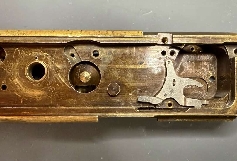
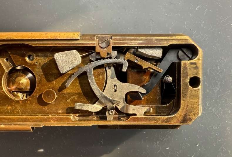
To remove the shutter from the camera, the entire escapement mechanism, including the gear segment and its torsion spring, had to be removed first. The viewfinder also needed to be taken out. Only then could the shutter be slid out of the base body to the right:
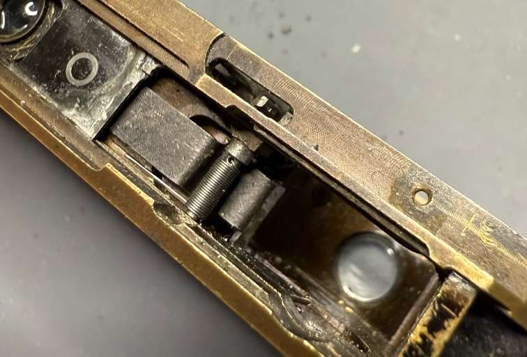
The torsion spring of the gear segment is clearly visible in the centre of the image. In front of the spring, pressed into the two grooves above and below the spring, is a small metal bridge that can be easily pulled out towards the front.
Unfortunately, the shutter was beyond saving. This delicate and highly precise component, consisting of two parts, only further underscored the extraordinarily high technical standard of this camera.
The shutter frame was already broken in several places and the shutter blade in two places. Attempts had already been made to solder them back together, but unfortunately to no avail:
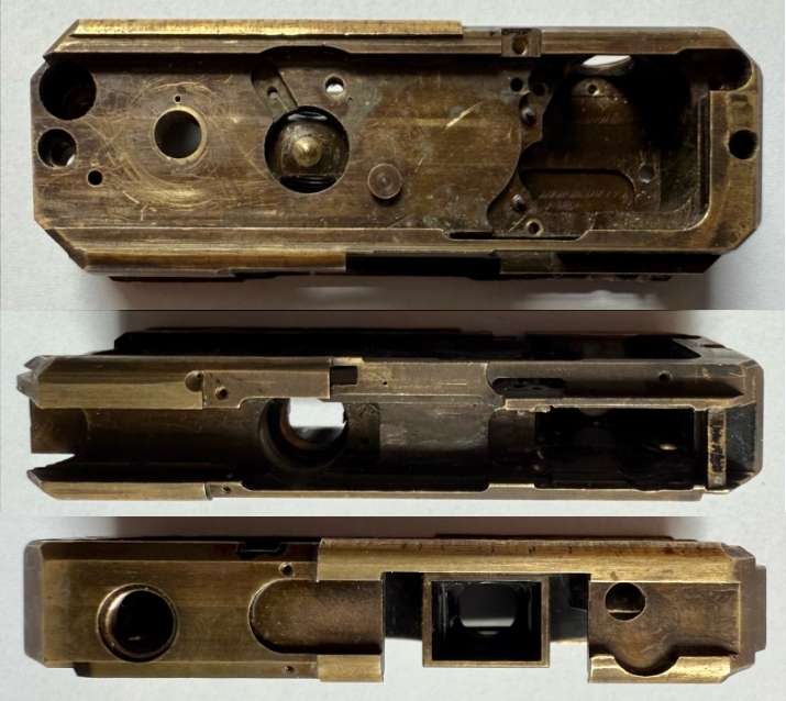
Once the shutter was removed, the remaining components could be taken out, leaving the camera chassis completely “bare” before me. It was a fascinating moment that instantly transported me back to the camera’s production in 1940.
Restoration of Components
With all components cleaned, the next step was to repair damaged parts where possible or replace them. For missing components, I first tried to source them from the very limited market. When that wasn’t possible for several parts, I decided to recreate them as accurately and faithfully as I could.
For simple components like screws, this wasn’t too difficult, but critical parts like the shutter blade and the yellow filter posed a massive challenge.
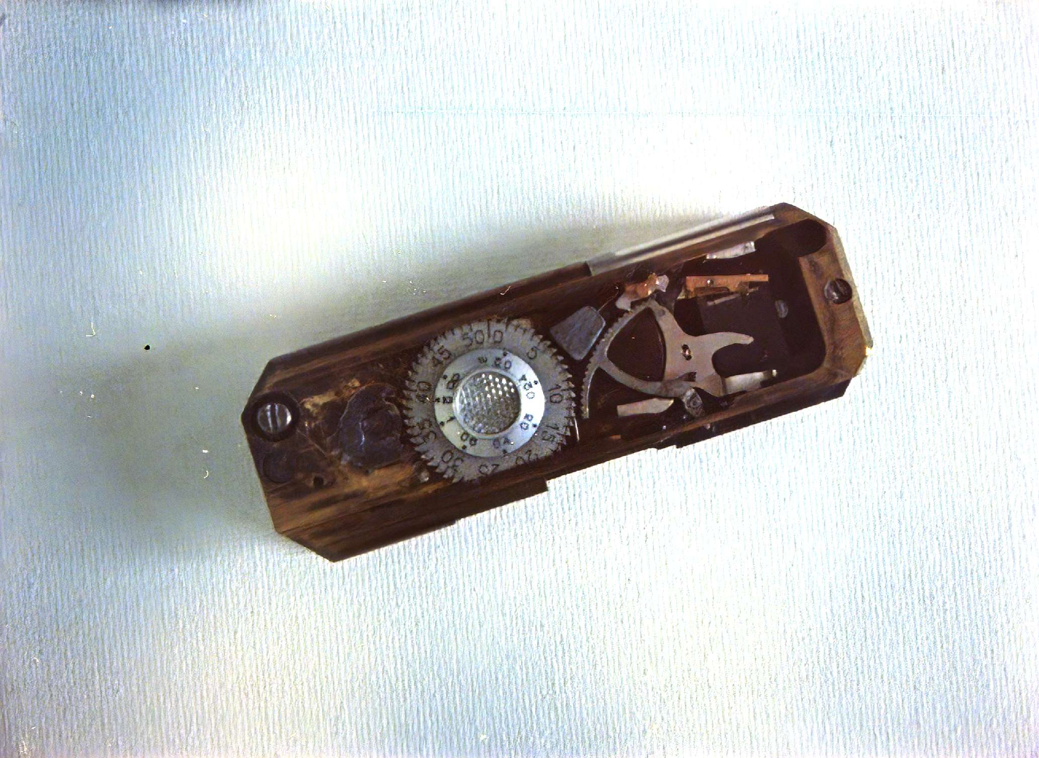
Distance dial and frame counter
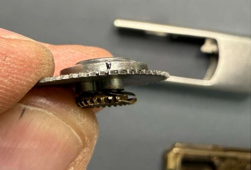
The most difficult task, however, was reassembling the disassembled distance adjustment unit, which included the bevel gear, adjustment dial, and the frame counter disc in between, into a single component. Unfortunately, someone had completely dismantled the soldered unit comprising the distance setting and the counter disc of the image counter:
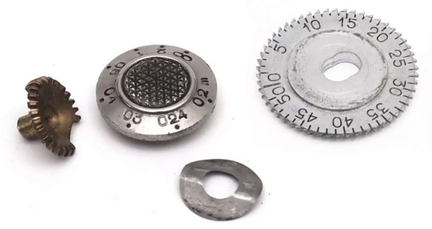
The main challenge here was determining the exact alignment of the distance markings with the bevel gear, as well as precisely centering and soldering the bevel gear to the adjustment dial at the correct height. The connection is also under slight spring pressure from a special spring washer between the bevel gear and the counter disc.
It took at least six attempts to get it somewhat right. The centering and alignment of the distance adjustment weren’t perfect without specialized tools, but they were acceptable. In production back then, a specific jig was surely used for this complex component assembly.
For some reason, the pawl for the film advance had been brutally bent, rendering it non-functional. With some patience and gentle pressure, this component could be restored, regaining its original appearance and intended function.
Shutter
Next up was the shutter. As mentioned earlier, it was completely unsalvageable, so both parts had to be sourced anew. I was lucky to find a shutter frame, but the shutter blade was no longer available, so I had to take matters into my own hands.
It would have been easier for the camera’s developer to make the shutter from a single piece, but that would have increased the moving mass significantly, making the extremely short shutter speed of 1/1000 second—remarkable for its time—difficult to achieve.
Thus, they opted for a two-part shutter, consisting of a delicately machined frame and an ultra-thin shutter blade. Fine grooves were milled into the frame, into which the blade was later inserted and spot-soldered. In production, the blade was likely punched out with a special tool, which would have been laboriously crafted. Today, it’s possible to produce small quantities relatively easily with laser cutting, but few suppliers can handle such small components and thin materials.
Once both parts were finally available, they could be soldered together, replacing another critical but defective component.
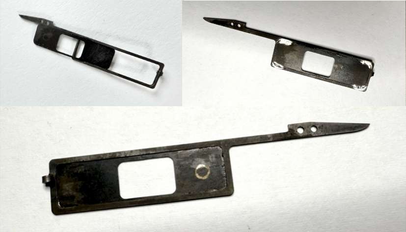
top right: soldering of the blade,
bottom: the finished shutter.
Another component that had given up the ghost was the shutter spring, of which only fragments remained, barely hinting at its former function. The spring was recreated, and a special winding core was made for it. After several attempts, the spring’s windings were correct, and its shape was perfect.
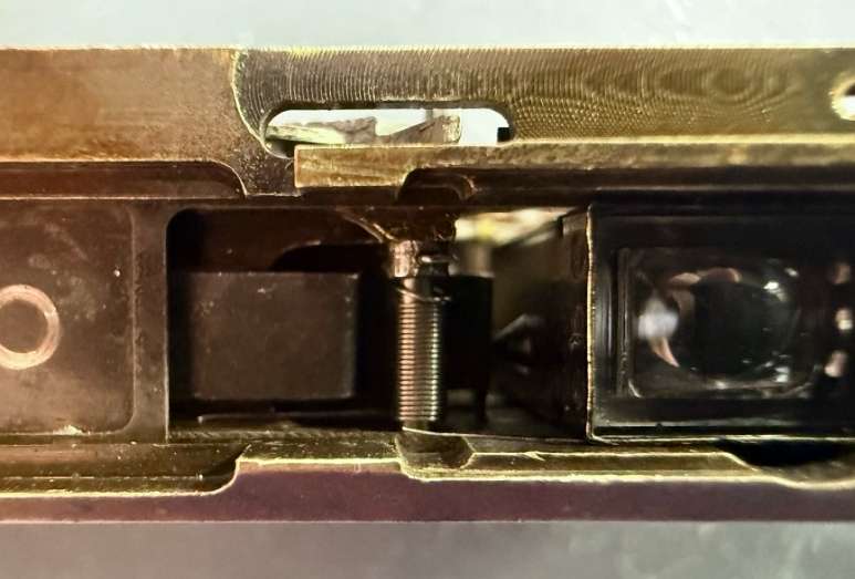
Now, the spring had to be soldered to the lower core, which holds the fixing screw for the spring and the dark slide in the movable housing element.
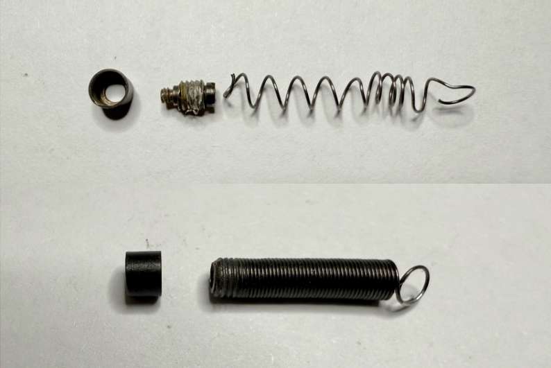
below, the newly wound shutter spring ready for use.
Filter glass
The greatest effort in restoring the camera went into replacing the glass yellow filter. The challenge wasn’t just sourcing a two times yellow filter material but also crafting it to the required dimensions. Attempts to have it made failed due to minimum order quantities and the cost of custom production. So, I had to resort to making it myself.
The filter glass was available on the market, but not in the required size or thickness. The size was relatively easy to achieve, and the necessary hole at the edge of the glass was challenging but feasible. Reducing the material’s thickness and then polishing it to optical clarity without significant scratches, however, seemed nearly impossible. It’s worth noting that hardly any Minox Riga yellow filter remains completely scratch-free after 85 years.
Many attempts were needed to find the right technique and sequence of grinding media to achieve an optimal result. The material was first ground thinner on diamond grinding plates.
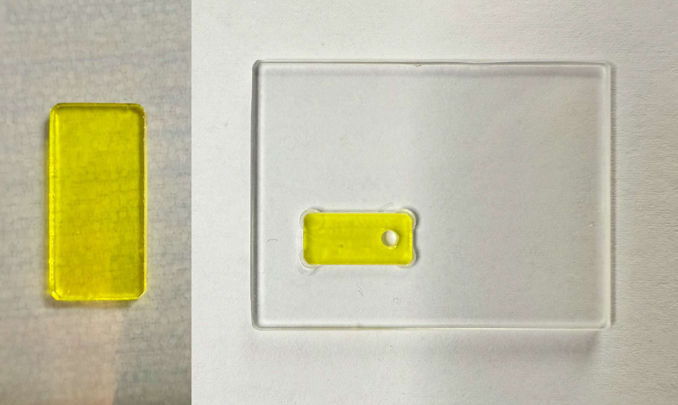
on the right is the manufactured drilling template with a drilled filter glass.
It was crucial to maintain uniform thickness across the entire surface, so sacrificial glass pieces of the same thickness were placed around the filter glass, and their thickness was constantly measured during grinding. Finding the right approach and materials for the final polishing of the filter was also difficult and required several attempts to achieve satisfactory quality.
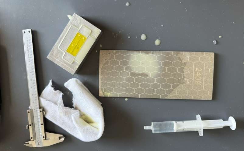
In the top left corner, you can clearly see the sacrificial glasses surrounding the filter glasses, which serve to ensure a flat surface when reducing the thickness.
Assembly
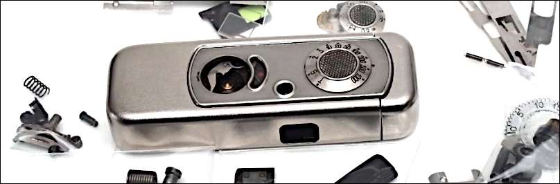
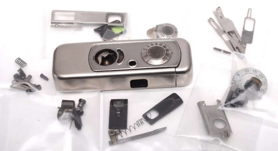
All parts were now restored, replaced, cleaned, and ready for assembly. To capture an image of all the components of a VEF Minox Riga, they were arranged on a plate in their approximate assembly positions and photographed. The result was a beautiful image and a tribute to Walter Zapp, who created this fantastic camera that was ahead of its time in design and technology.
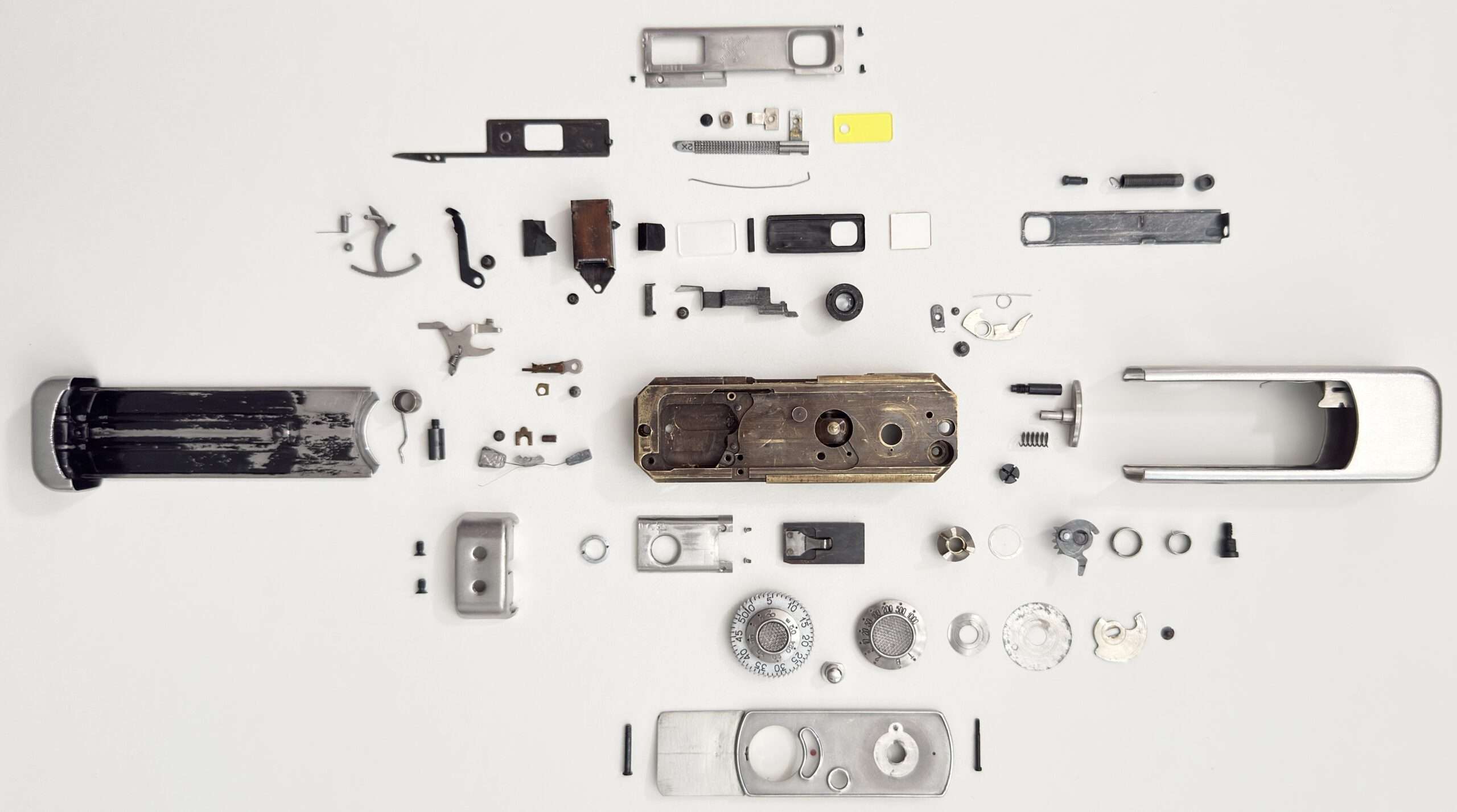
All parts of the VEF Minox Riga are ready to be reassembled into a functioning camera.
Shutter release lever
First, the release lever, mounted on two points and held under tension by a pull spring, was installed. The spring isn’t just hooked in; it’s firmly connected to the chassis base via a soldered wire connection.
soldered wire.
mounted on two points.
Lens
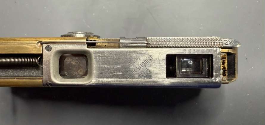
Next, the lens, a Minostigmat was inserted, and the parallax compensation lever was mounted. When screwing in the lens, ensure that the thread is positioned so that the end of the thread is visible when the lens is fully screwed in:
Shutter
Then, the new shutter was slid into the chassis guide from the right. So far, so good… the shutter is back in place:
The assembly continued with the viewfinder, its side spring, and the spring hook above it.
Esapement mechanism
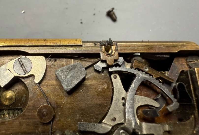
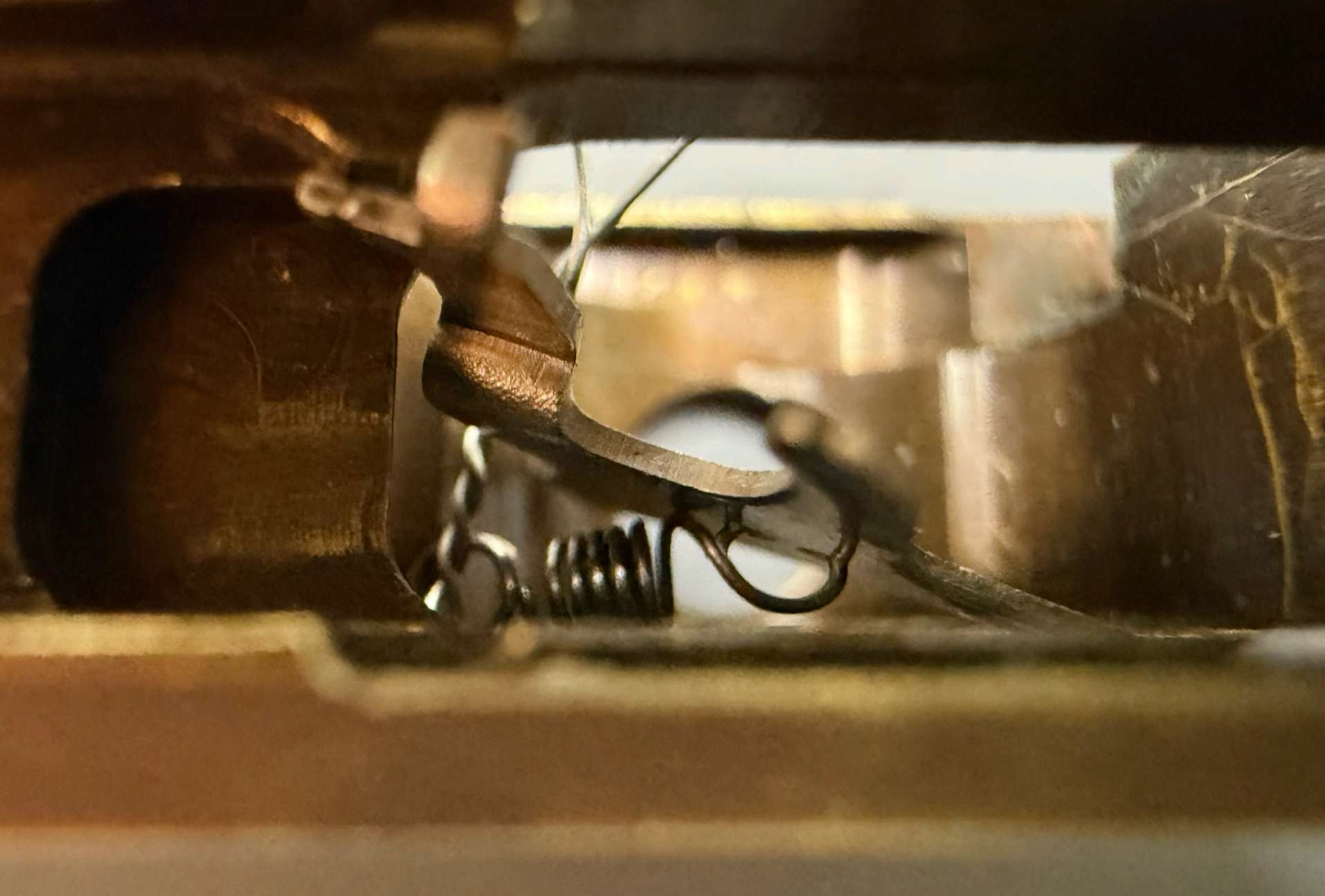
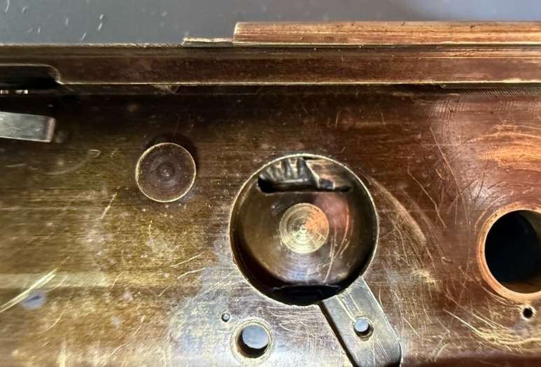
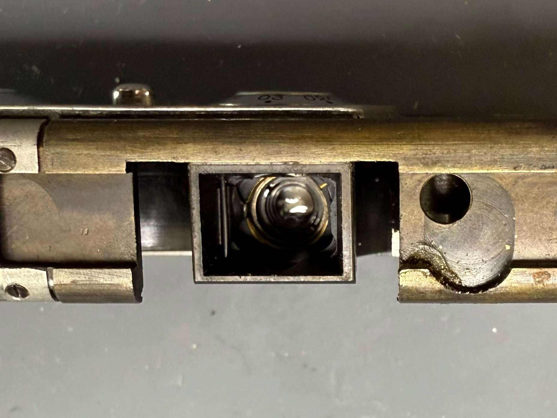
Now, the entire escapement mechanism had to be reinstalled. The torsion spring and the tiny flange above the gear segment’s spring were a bit tricky, but with some patience, they were back in place. The flange is secured by a small wire inserted through the flange and the gear segment’s axle, preventing the axle from moving upward out of the guide bushing. In the center of the image, you can see the torsion spring on the axle of the gear segment and, above it, the small flange that is secured with a piece of wire:
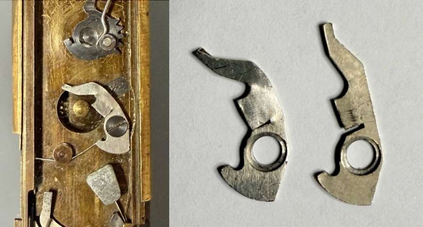
Now, the entire escapement mechanism had to be reassembled and aligned. Starting with the small copper-colored anchor that moves on the right side of the gear segment, followed by the left anchor with its two lead weights, which runs ahead on the gear segment. The order is critical because the mounting screw for the right anchor becomes inaccessible once the second anchor is installed. Several attempts were needed to ensure both anchors moved smoothly and effortlessly on the gear segment.
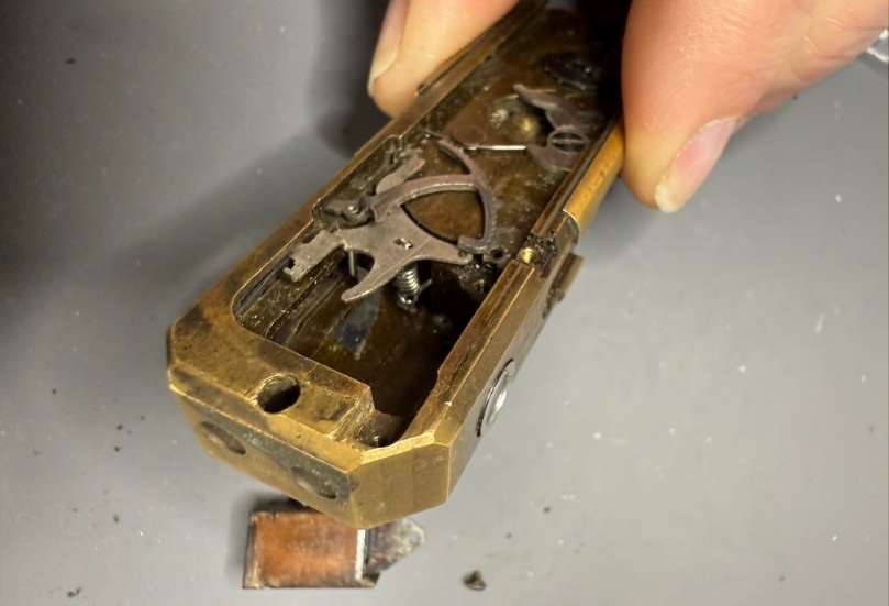
To test the shutter and the entire escapement, a special part was made into which the dark slide with the shutter spring could be screwed. This allowed the shutter to be cocked without the camera housing attached. Now, the shutter spring just needed to be hooked in, and the shutter could be seen closing while the escapement hummed in all its glory.
The shutter speed in this setup should be around 1/2 second, which can be tested fairly well. If it’s close enough, nothing stands in the way of further assembly.
The following two videos show the shutter in action. First, we see the movement of the shutter and some parts of the escapement in the overall view:
The next video shows the escapement in detail at work:
Film transport
Correct film transport is extremely important, as otherwise, if there is an error in the film feed, the distance between two frames on an exposed film can become too small and, in the worst case, the images can overlap. This can render an exposed film completely unusable, as can be seen in the image below.
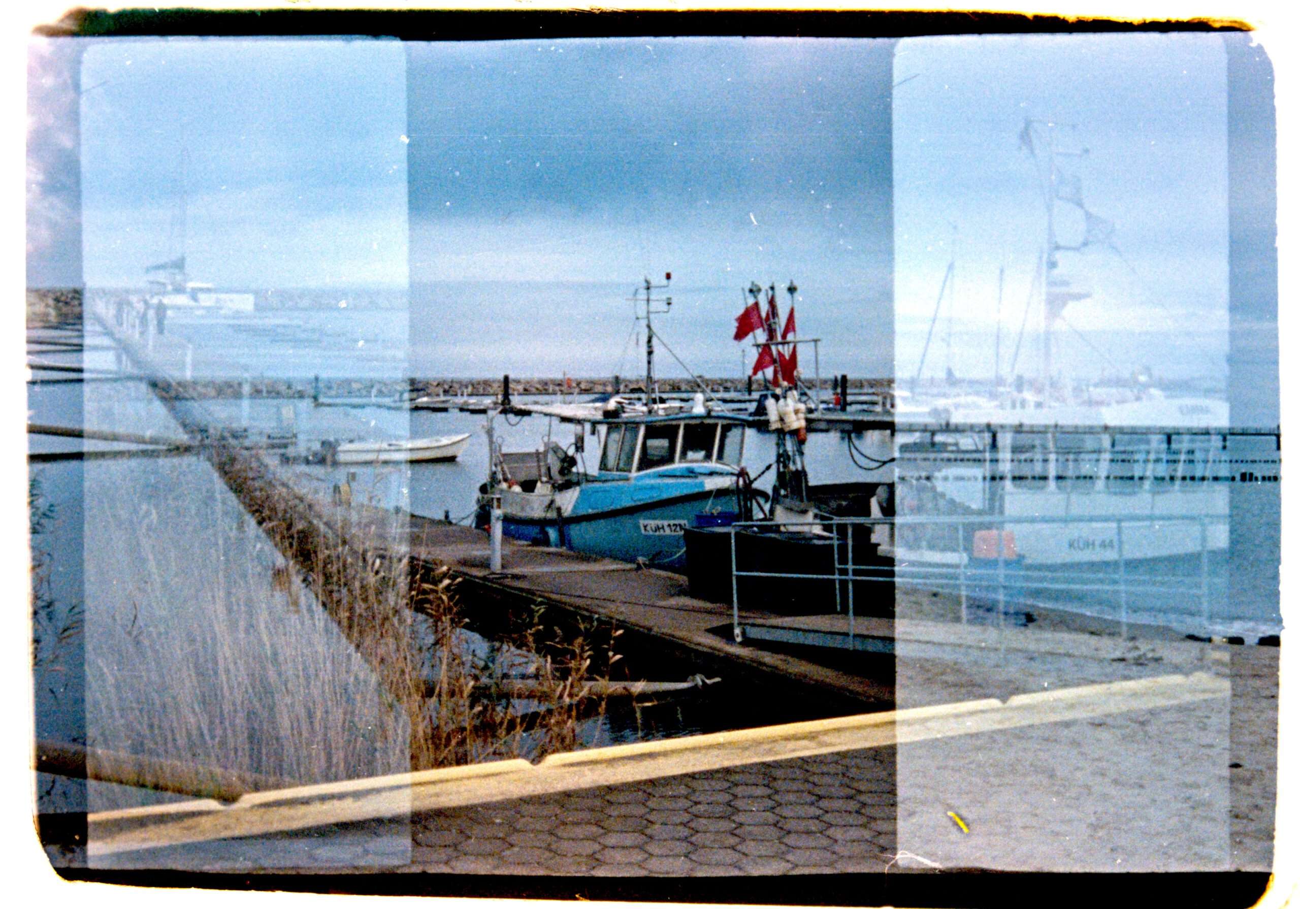
Unfortunately, this was extremely the case with this camera, and additional troubleshooting for the film transport area was therefore necessary.
As the camera had been treated rather roughly in some areas and the supplied parts included a completely worn and defective film transport gear segment, I had to assume that brute force had also been used in the film transport area.
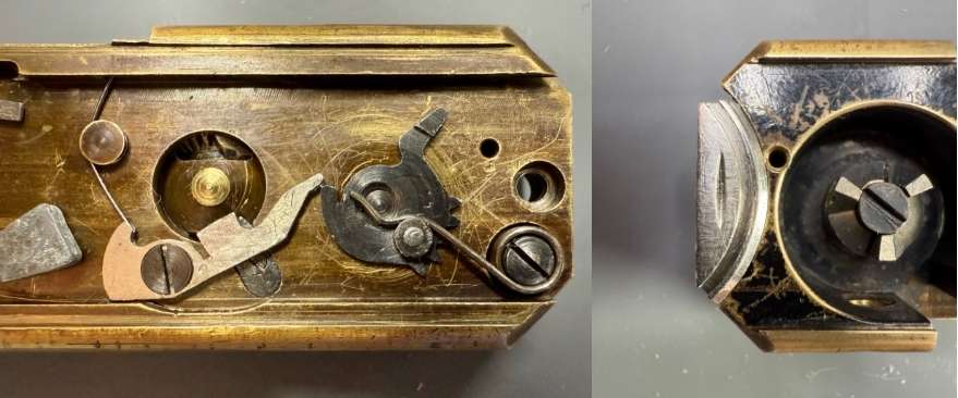
The picture on the left shows the bent pawl and a new film transport gear segment, which appears to have been replaced for the worn and defective film transport gear segment shown in the picture on the right.
Unfortunately, the axle of the new part did not fit correctly into the borehole in the chassis and jammed. In addition, the enormous force that was apparently applied here also destroyed or bent the film transport gear segment and the pawl, as well as warping the area in the chassis where the borehole is located. As a result, the axle of the film transport gear jammed in certain areas and could not be returned to its original position, even with the fairly strong spring force of the torsion spring provided for this purpose.
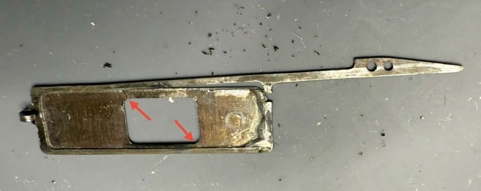
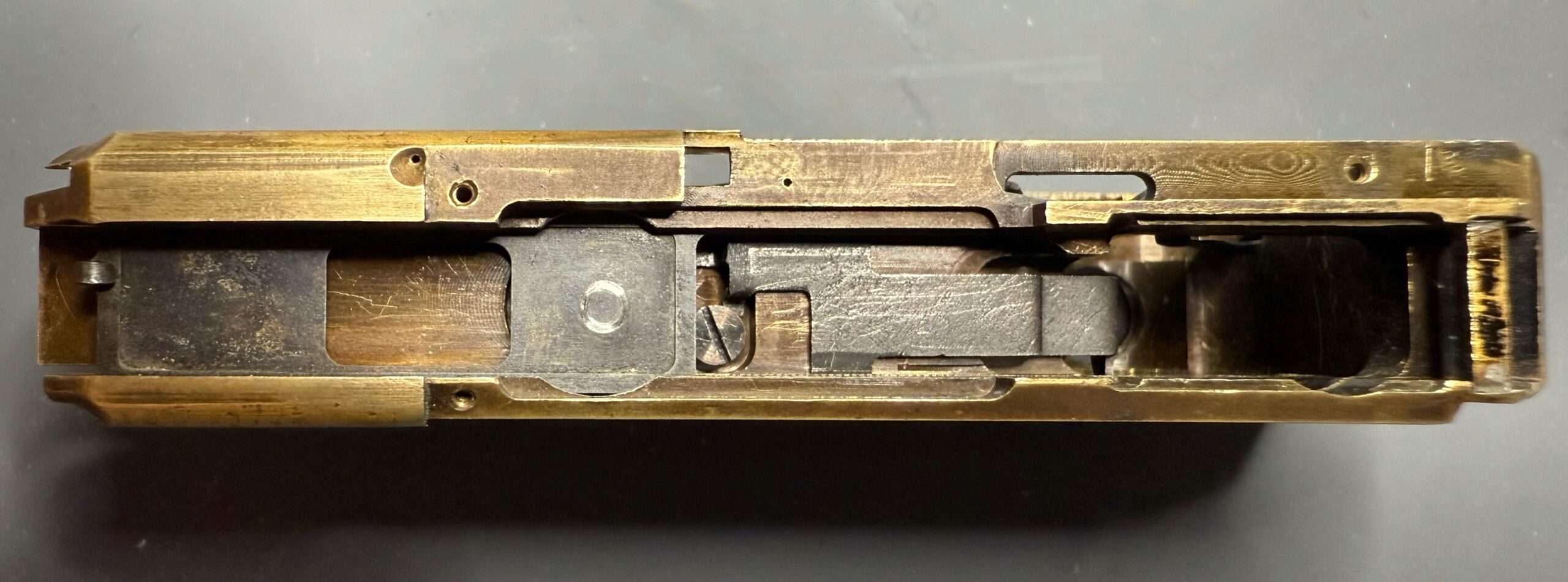
However, this is extremely important, as the rack, which is installed in the sliding sleeve, only engages with the film transport gear segment at a later stage.
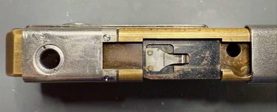
The first part of the transport stroke is performed by the head of the rack, which turns the protruding tongue of the film transport gear segment – shown in the yellow circle – until the rack engages with the teeth. The red arrow indicates the direction of the rack’s movement.
To ensure that the axis of the film transport gear segment ran smoothly, it had to be lightly sanded down and a thin washer had to be inserted under the fixing screw of the 3-tooth film transport wheel. After several attempts, the film transport ran smoothly and was returned to its original position by the torsion spring.
Next, the small guide plate and the pawl with spring for the distance adjustment were installed. The upper components of the film advance were then added.
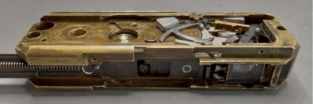
In the following left-hand image, you can see the pawl with spring at the bottom left, under which the guide plate is located. To the right of this, in the same image, you can see the film transport gear segment with the strong torsion spring. In the right-hand image, you can see the film transport wheel with internal springs and the film compartment lock from the underside:
Now, the film advance wheel with its flat teeth and two special springs could be inserted and screwed in from below. Finally, the opening mechanism for the film compartment was installed.
Three methods were used to test the success of the repair. First, a round cardboard disc was glued to the 3-tooth transport wheel and an initial mark was made. Then the film transport was carried out via the sliding sleeve and the second mark was made on the round cardboard disc (the following two images show a Minox A):


The two marks now form an angle that can be measured accordingly. If this process is carried out at frame counters 1, 25, 36 and 50, the following results are obtained:
The angle decreases as the frame counter increases, because the film transport is automatically corrected to the corresponding film reel thickness via a cam wheel on the underside of the frame counter disc and the pawl running on it, thus keeping the distance between each exposed frame constant – but of course with certain acceptable tolerances.
The measurements yielded the following results, all of which are within the tolerances:
| Frame counter reading | 1 | 25 | 36 | 50 |
| Angle in degrees | 130 | 115 | 100 | 92 |
In order to confirm the success of the repair with a second different test, an old unexposed film was sacrificed and transported completely through the camera.
For each new frame counter reading, a mark was made on the exposure window in the area of the film pressure plate on the left and right and labelled with the frame counter reading. The result is a complete image of the individual frame positions on the film.
Since the outer edges of the exposure window were marked, but the actual optical window is smaller, a gap automatically appears between two exposed frames.
In the image above, you can clearly see the optical image window, which is smaller than its outer contours.
The film, labelled and marked in this way, was then removed, unrolled and measured. The result was a film advance of approximately 12 mm between each mark and a total length of the film from the beginning of mark 1 to the end of mark 36 of 453 mm, which corresponded to an average length of 12.58 mm per transport stroke and a space of 1.58 mm between the frames.
The third and final test, of course, involves exposing a roll of film. And as the first two tests predicted, there is no overlap anymore. In fact, the intervals between shots are almost perfectly even from the first to the last frame:

This shows once again how precisely the Minox mechanism works.
Distance dial
Then, the distance adjustment wheel, as a unit with the frame counter disc, could be inserted. To make this easier, the spring of the film advance gear segment should be disengaged and locked into the chassis at the back – be careful, the spring force is quite strong. Then, rotate the gear segment with the long tongue to the left until the pawl is completely clear of the opening for the distance adjustment’s bevel gear.
Next, rotate the lens nine teeth to the right, ideally using a toothpick to avoid damaging the lens’s gearing. The valley between teeth 9 and 10 should now be vertically centered in the opening. Hold the distance adjustment wheel between 0.4m and 0.6m at the 3 o’clock position, and rotate the frame counter disc until it moves as far left-upward as possible from the axle’s center.
Then, insert the distance dial slightly tilted forward into the opening, ensuring the frame counter disc dips into the front groove of the chassis. The distance dial should now be pressed easily downward. If it doesn’t, gently rock the adjustment wheel back and forth until the bevel gear engages with the lens’s gearing. Once engaged, lightly press the frame counter disc downward and slide it to the right-down into the rear groove of the chassis, so it sits centered on the axle again.
Once the frame counter disc is in the lower groove, the pawl, which was pressed down with the film advance gear segment, can be re-engaged. This is done by rotating the gear segment back to the right until the long tongue is at about 12 o’clock. Then, carefully re-engage the spring for the gear segment above the round guide roller.
To test whether the distance dial and bevel gear are correctly engaged with the lens’s gearing, set the distance to infinity and observe whether the lens rotates correctly and reaches the infinity setting.
Do the same for 0.2m, ensuring the adjustment wheel isn’t turned too far, as this could cause the lens to jump out of the thread and prevent it from rotating back into the chassis. If this happens or both settings aren’t reached, the bevel gear isn’t correctly positioned in the lens’s gearing, and the entire process must, unfortunately, be repeated.
Control plate
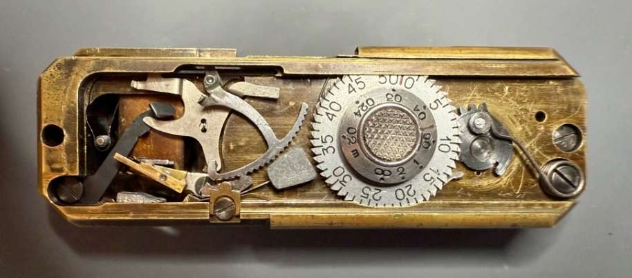
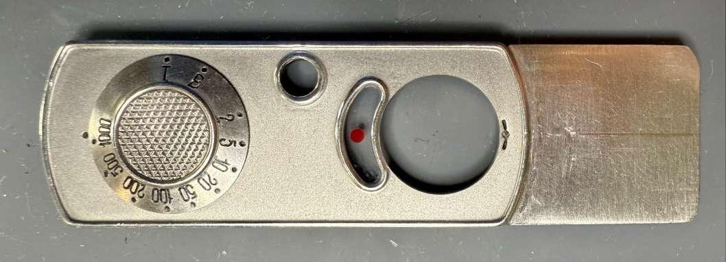
Once this step is complete, the upper control plate, with the shutter speed adjustment wheel correctly mounted and the release button inserted, can be reinstalled. Here the control panel without the release button, almost ready for installation:
Yellow filter
Now, the holder for the yellow filter and the lens glass can be inserted, next the viewfinder glass, with its beveled long side pointing downward, can be installed.
The yellow filter runs on the lower level and slides under the lens protection glass, which is fixed in position on the upper level by two small pressed-in edges.
After the filter glass and lens protection glass are inserted, the front plate with the slider for the yellow filter can be mounted. Ensure the slider correctly engages with the hole in the filter glass. To make the third screw located under the slider visible, push the slider all the way to the left and pull it slightly upward. Proceed with extreme caution, as the hole in the filter glass can break very easily:
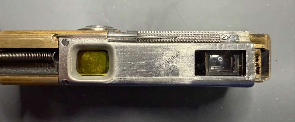
After assembly, carefully check if the filter can be easily moved to both positions. Now we see the yellow filter in the inserted position:
Back plate
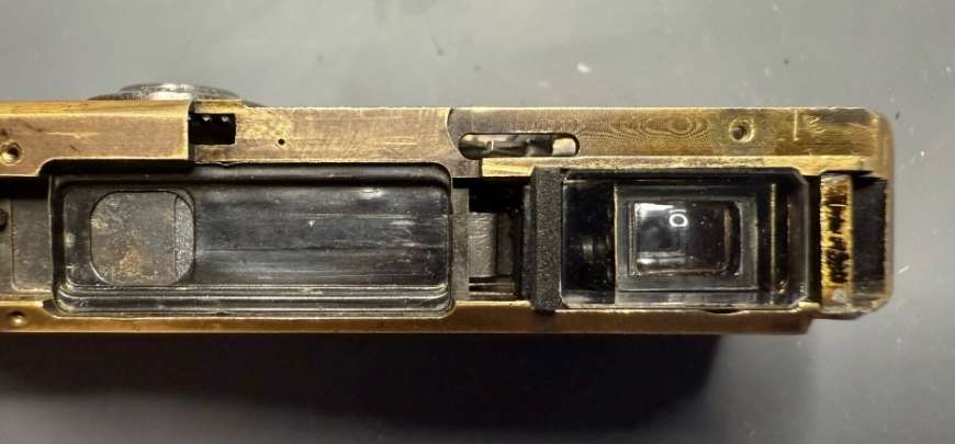
Now, mount the back plate with the round viewfinder lens and insert the film pressure plate. Then, screw the dark slide and shutter spring into the sliding sleeve of the camera housing. Both components remain slightly rotatable when screwed in and can be aligned before insertion. The plate for the viewfinder lens looks a little worn, but after 85 years, it’s only natural that it should show a few scars from the passage of time:
Hooking the shutter spring
To simplify hooking the spring, a thin string can be threaded through the shutter spring’s loop and pulled outward through the lens opening. To prevent the shutter from being pushed back while hooking the spring, another thin string can be threaded through the shutter’s loop and pulled in the opposite direction.
Inserting the sleeve and hooking the shutter spring practically requires five hands, making this the most nerve-wracking part of the entire assembly. Patience is key here.
First, push the dark slide into its designated groove. Then, slide the sleeve further in, ensuring the rack inside the sleeve engages with the correct opening and the film pressure plate is properly seated in the sleeve. You should now see the shutter spring and shutter through the lens opening.
The rest requires finesse to hook the spring’s loop over the shutter’s loop. Once done, carefully remove both strings. If everything is correctly assembled and aligned, the sleeve can now be fully inserted until it stops.
Before tensioning the shutter for the first time, screw in the sleeve’s lock in the film compartment to prevent accidentally pulling the sleeve out too far, which could easily damage the new spring or shutter.
Housing
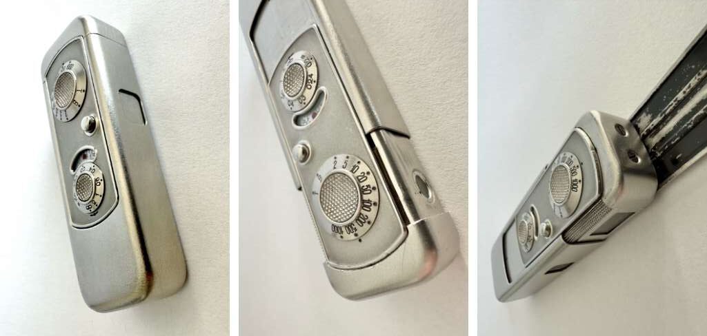
Finally, mount the film compartment slider with its cap, which also serves as a lock. Of course, test all shutter speeds and the film advance, and then you can fully enjoy the VEF Minox Riga in all its restored beauty:
Test photos
The ultimate test of whether a camera repair has been successful is to expose a roll of film. Only then can you assess whether shutter, escapement, lens adjustment, and film transport are working correctly. Take a look at the pictures that were taken after the restoration of this pile of VEF Minox Riga parts on a Kodak Ektar 100 film (click to enlarge):


Please note that these are snapshots taken by hand without a tripod. If you are interested in the objective performance of the Minostigmat lens of the VEF Minox Riga, read this comparison test between Minostigmat and Complan lenses.
This is not a repair manual, but rather a presentation of a camera project. If you plan to repair your Minox yourself, please read our Legal Disclaimer before you repair.
Conclusion on the VEF Minox Riga repair
Burkhard’s four-month endeavor to restore a dilapidated VEF Minox Riga exemplifies extraordinary dedication and technical prowess, transforming a near-hopeless relic into a functional masterpiece. His labor-intensive project demanded not just mechanical skill but also ingenuity in reverse-engineering scarce components.
The restoration also underscore his respect for Walter Zapp’s engineering genius, elevating the work from mere repair to a preservation of this historical innovation. Equally impressive is the restoration’s precise, step-by-step description, which serves as an invaluable information for enthusiasts.
I would like to thank the author for his permission to publish his report here on Moments-of-Now for the first time and exclusively.
Further articles on the VEF Minox Riga
- If you are interested in the mechanics of the shutter on a VEF Minox Riga, you can find my detailed article on the subject here.
- Here I present my own VEF Minox Riga and its design principles.
- In 2024, I conducted a comparison of the two Minox lenses Minostigmat (VEF Minox Riga) and Complan (Minox A), which had never been done before. The results are presented here.
VEF Minox Riga links
- The Museum of Modern Art
- Westlicht 3D Kamera-Museum
- Wikipedia article
- Latvian newspaper article from November 2, 1938
- Latvian newspaper article from February 25, 1939
- submin.com
- MinoxDoc.com
- JulianTanase.com