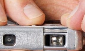
The smooth release of the shutter has always been a special feature of Minox spy cameras. This is, of course, crucial for holding the camera steady at the decisive moment. On the other hand, the shutter release must not be so easy to press that it is activated accidentally. In this article, we will see how these two conflicting requirements have been perfectly resolved here.
Page Contents
The trigger design
Half of the trigger (green circle in the image below) rests on the release lever 2a. The other half rests on the spring plate 2b. The following image shows the complete exposure mechanism with shutter cocked. The escapement lever 4a is spring-loaded toward the center of the housing. It is held in place at point 4a by the release lever 2a.
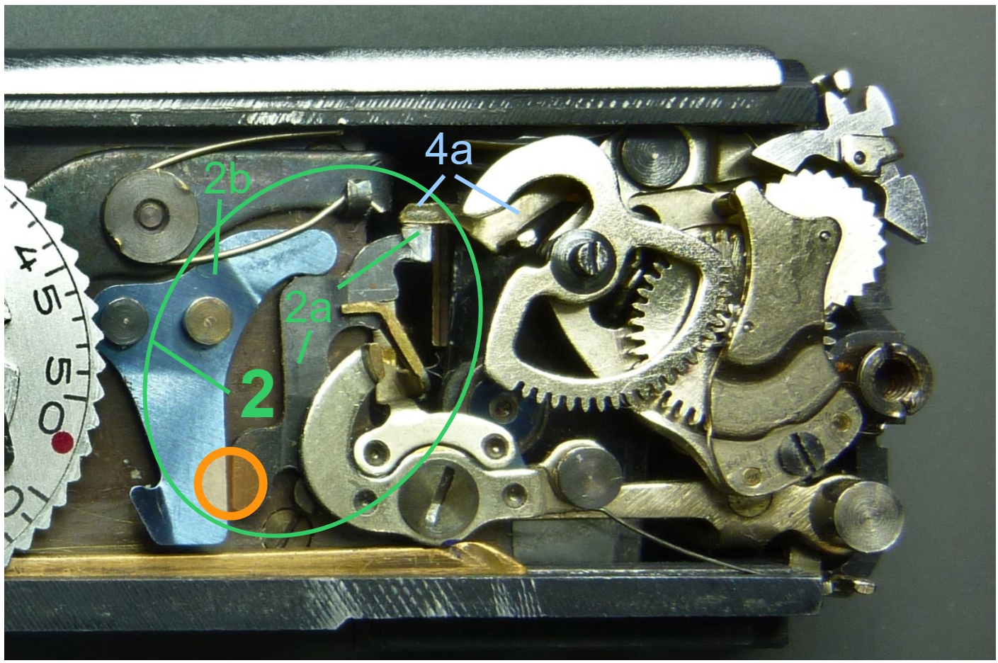
When the release lever is pressed, it does so against the resistance of the spring plate. At the same time, the end of the release lever is lifted, thereby releasing the escapement lever 4a. When the release lever is released, it is pushed back up by the spring plate.
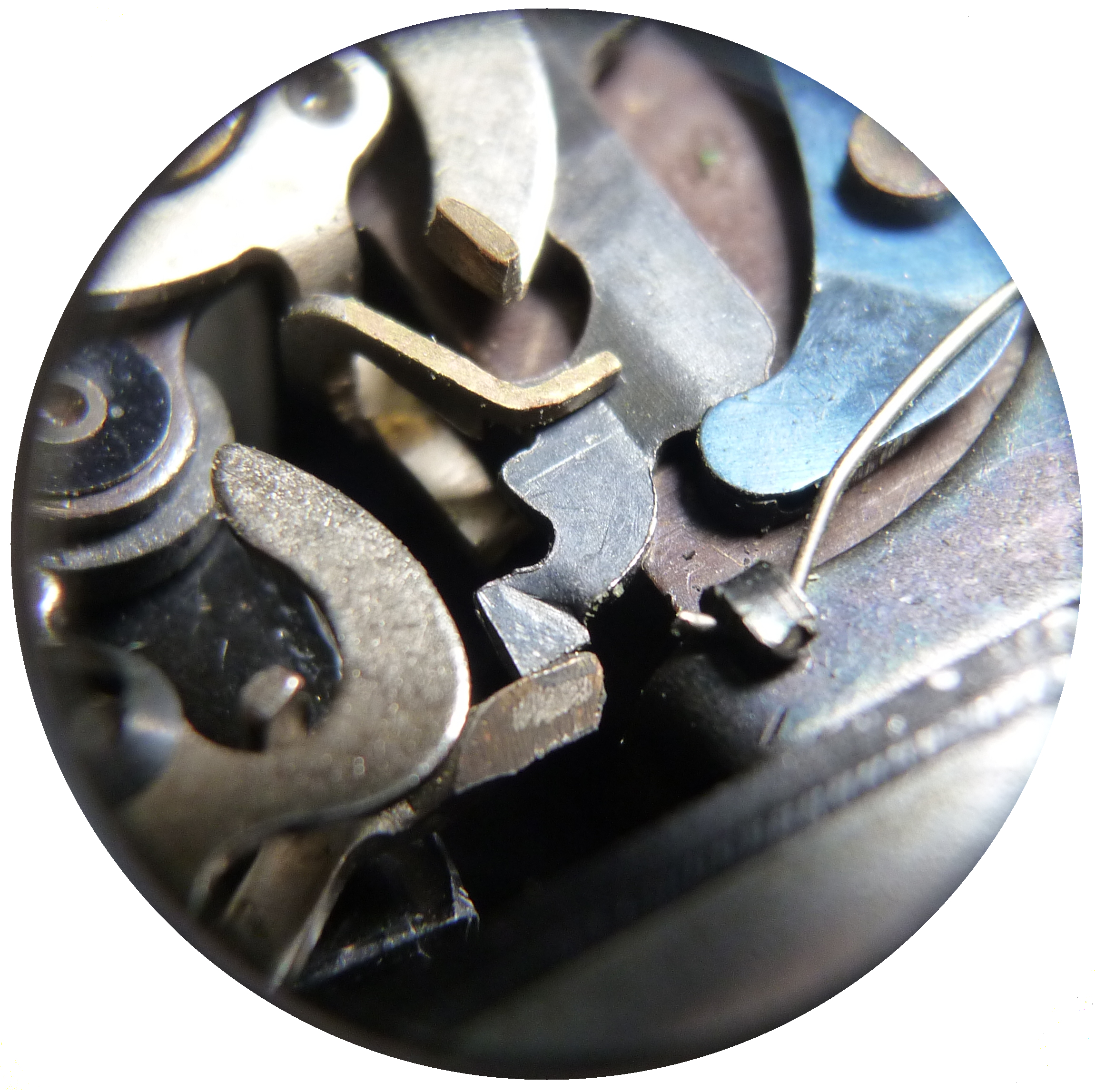
In the image on the right, we can see how the end of release lever 2a rests against the end of escapement lever 4a, thereby holding it in place.
The manual exposure modes “B” and “T”
The long-exposure modes “B” (Bulb) and “T” (Time) on analog cameras are designed for extended shutter times, allowing photographers to capture images in low-light conditions or create specific effects like light trails or star trails.
- Bulb (B): The shutter remains open as long as the shutter release button is held down, giving the photographer precise control over exposure duration. It’s ideal for unpredictable or very long exposures, such as fireworks or night photography.
- Time (T): The shutter opens when the shutter release button is pressed once and closes only when pressed again, allowing hands-free long exposures. This is useful for extremely long exposures, like astrophotography, where the camera needs to remain steady without continuous manual input.
Implementation in the Minox
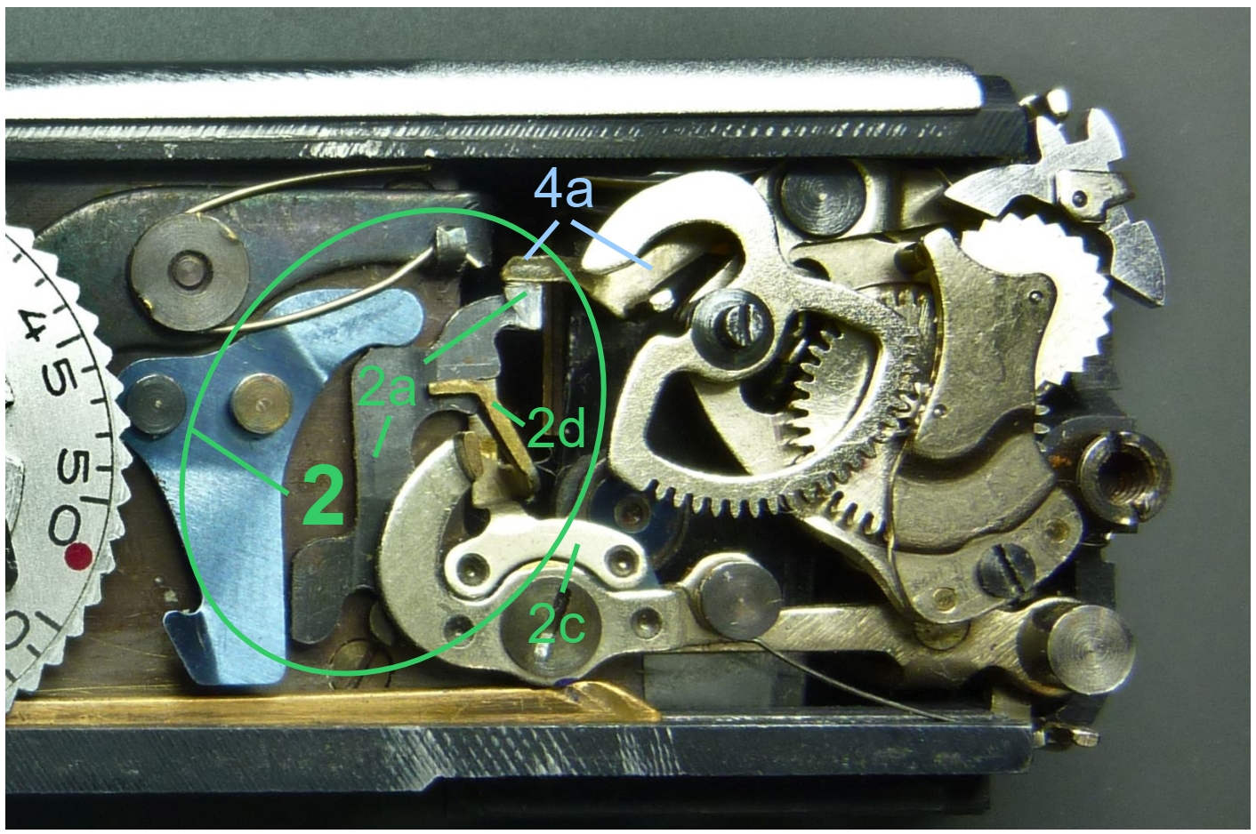
The two-part long exposure lever 2c implements the exposure times “B” and “T.” It blocks the swivel movement of escapement lever 4a as soon as the first blade has been released.
In this position, the lens is open. When in preset “B” the shutter button is released by the user, 2c immediately releases 4a. In preset “T”, 2c engages when the user presses and releases the shutter button. Only pressing it again releases escapement lever 4a.
In both cases, the swivel movement of 4a continues for 0.5 s before the second shutter blade is released and the lens closes. This is because the starting position of the escapement for “B” and “T” is at 1/2 s, see following images.
The long exposure lever
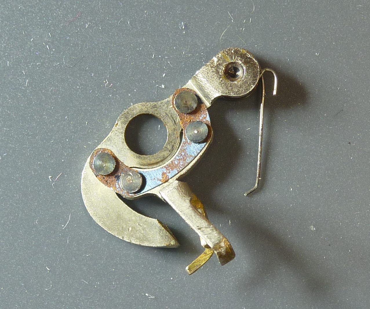
The following two images show the long exposure lever 2c from above and below. In the top view, the two arms ratchet is clearly visible on the right. In the bottom view, the connection of the ratchet to the rest of the part via a spring plate is visible. The spring plate allows the ratchet to move up and down with the trigger lever 2a when the release button is pressed.
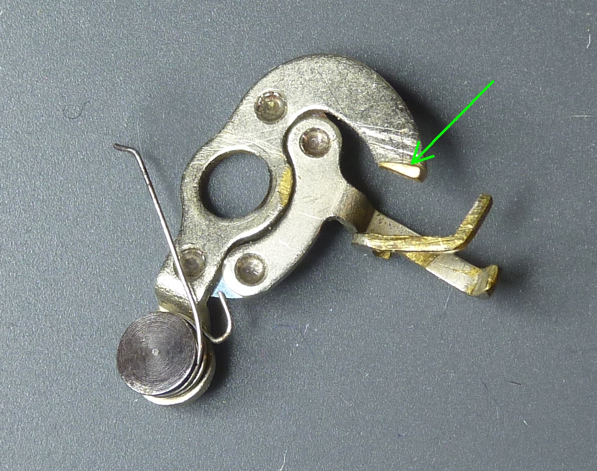
green arrow: pin for shutterspeed dial
The exposure presets “B” and “T” are achieved by temporarily or permanently blocking the escapement lever 4a after starting the first blade that opens the lens. A sophisticated three-dimensional two-part ratchet ensures this. When the user releases the shutter release button (“B”) or presses a second time (“T”), the escapement lever is released again and can start the second blade, which closes the lens.
Transferring the presets to the trigger mechanism
The two modes are selected on the shutter speed dial. The cam disc inside the camera, which is permanently connected to the shutter speed dial, has a specially shaped hook in the range beyond 1/2 s. In the “B” and “T” positions, this engages with a pin of the long exposure lever 4b (see image above, green arrow).
We can see these presets in the following images in a special view. It is a view of the shutter speed dial from below, but mirrored so that the view matches the image above. The green circle corresponds to pin screw 1 there and represents a shutter speed of 1/2 s. The red circle corresponds to the pin 2d of the long exposure lever 2c:
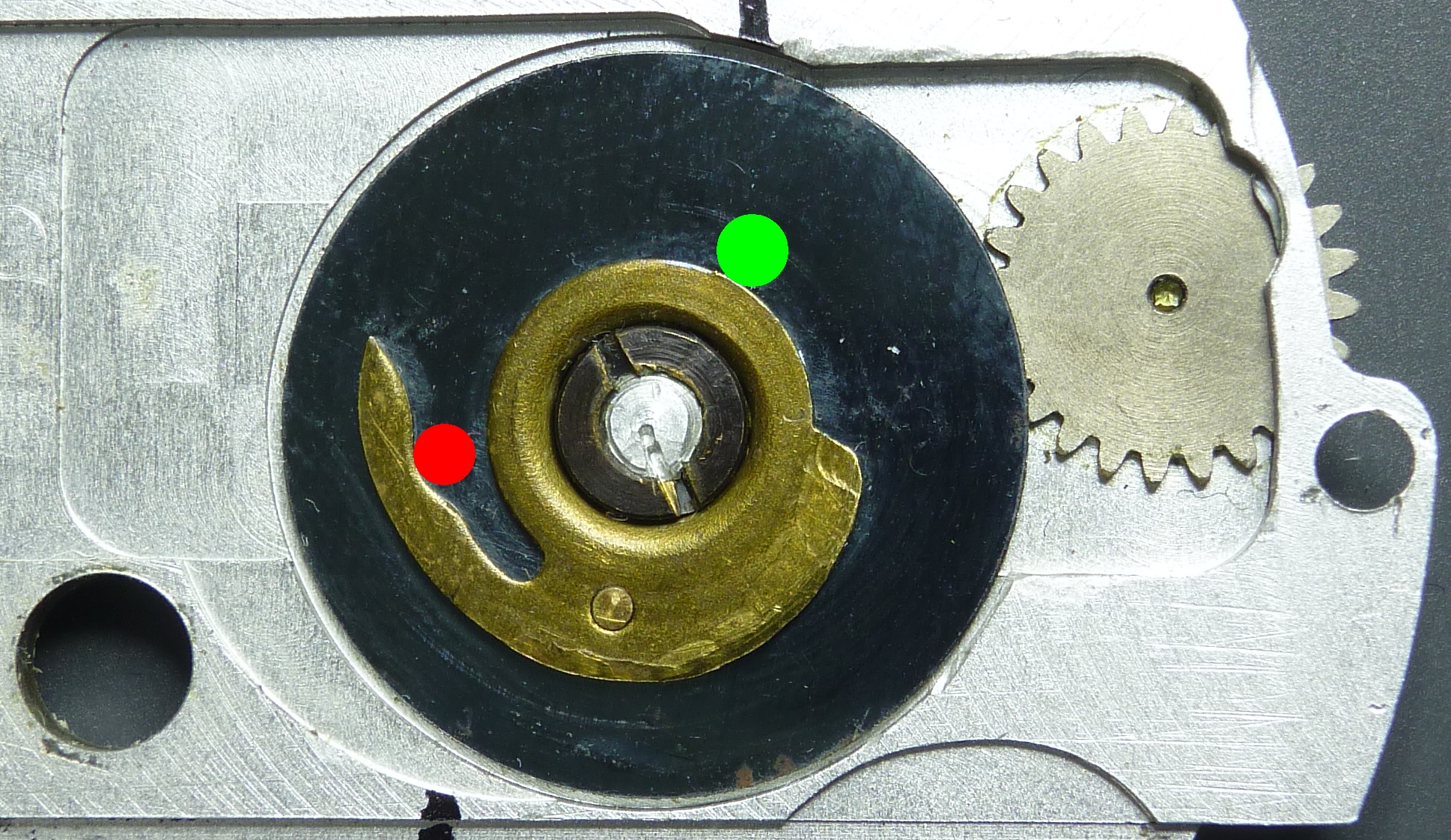
seen from below, mirrored
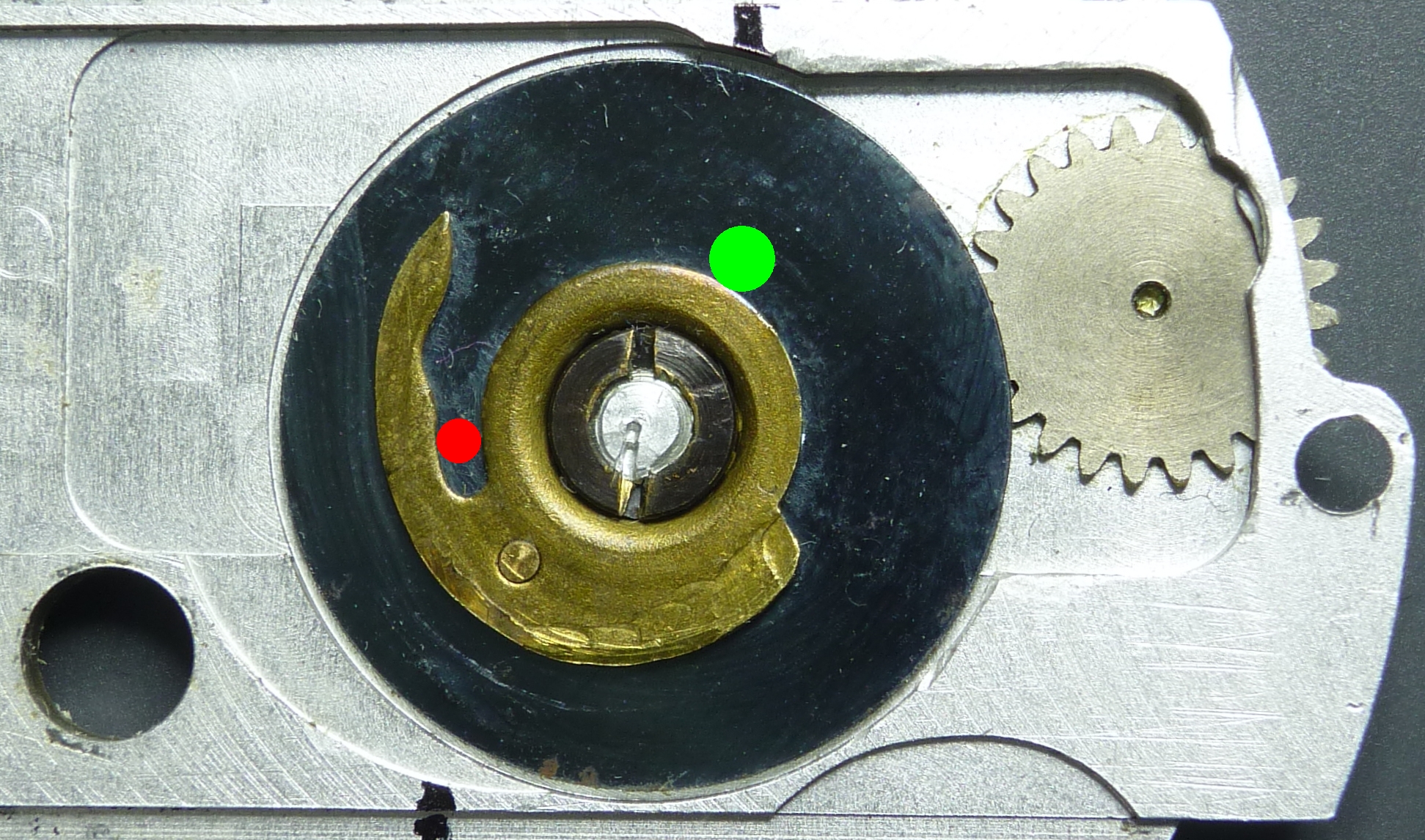
seen from below, mirrored
This enables the functions described above to be performed by the blade control.
Conclusion
The smooth but precise release of a Minox spy camera is achieved by a simple, balanced design consisting of a spring plate and a lever.
Considerable additional effort was required for the two long exposure modes. A two-part, three-dimensional ratchet mechanism, including control via the shutter speed dial, was necessary to achieve this.
Go to the next article How the Minox escapement works
Back to the article The minox exposure system