The lens that really shouldn’t have worked
Imagine you want to build the world’s smallest camera. A mechanical marvel, no bigger than a lighter. But there’s a problem: there isn’t a lens in the world sharp enough to capture an image on a piece of film the size of a fingernail.
The industry giants were in agreement. When Walter Zapp approached Agfa in the 1930s to jointly develop the lens, they coolly turned him down. Too exotic, too risky, simply unfeasible. At Leitz in Wetzlar, the Olympus of optics, they didn’t even deem a response necessary—they simply ignored him. To the experts in Munich and Wetzlar, the Minox was not a stroke of genius, but an optical pipe dream. A “lemon,” even before the first sketch was finished.
But while the market leaders were still explaining why the laws of physics were against Zapp, he found in Professor Hans Schulz someone who wasn’t intimidated by the big names. In his lab, Schulz set to work on a task that is almost forgotten today: he calculated the impossible.
He ignored the arrogance of the established players and designed a lens so sophisticated and tiny that it didn’t appear in any textbook.
It was the birth of the Minostigmat – a lens that wasn’t supposed to exist, but would change the world of photography.
At this point, I would like to thank Ralph T. Schwarz, without whose crucial clue regarding the identity of Hans R. Schulz this article would not have been written. Furthermore, his research into Schulz’s biography contributed significantly to a complete picture.
My special thanks also go to Heinz Humberg, who checked the entire physics of optics in my article and thus saved me from several errors in my presentation.
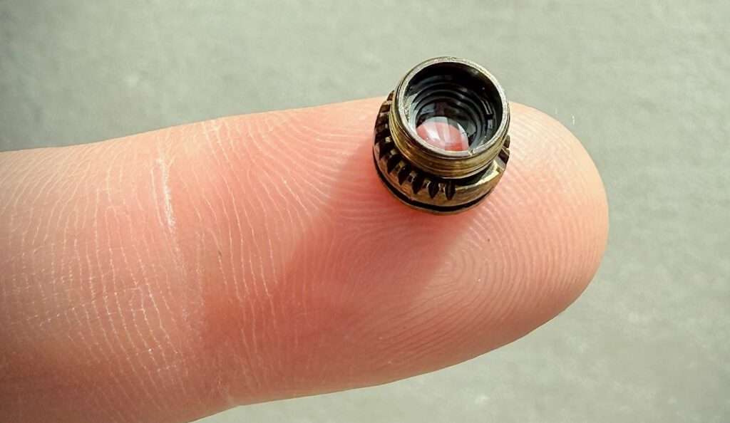
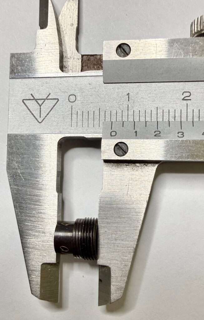
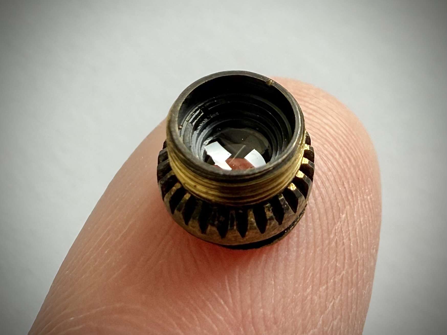
I thank Burkhard Fenner for the unique photos of the Minostigmat and the accurate dimensions.
Page Contents
- The lens that really shouldn’t have worked
- Who was the man behind the Minostigmat?
- The Minostigmat – Heart of the VEF Minox Riga
- Challenges for a lens
- Hans Schulz – The father of the Minostigmat
- Design and calculation of a Cooke triplet
- Result: The Minostigmat
- Conclusion
- Minostigmat test photos
- More information about the VEF Minox Riga
The Shadow Behind the Monument
Walter Zapp is a name that stands like a monument. His 1935 design for the VEF Minox Riga is considered the “Big Bang” of subminiature precision engineering—the birth of a camera that created its own legends. Yet every monument casts a shadow, and hidden within that shadow is the single component without which the Minox would have remained blind.
Search the standard literature for the origin of this eyesight, and you will encounter a silence that is almost provocative. Only a single, casual sentence in Heckmann’s Variations in 8×11 remains to remind us of the man behind the glass:
“After a grueling wait, these [the optical data for the Minostigmat] were finally calculated by Prof. Schulz in Vienna.”
It is a sentence like a footnote to history. It is all that posterity has left of the man who transformed Walter Zapp’s precision mechanics into a functioning tool. Zapp possessed the vision to build a camera that could disappear into a clenched fist—but he was no optician. He could design the mechanics, but he could not refract the light.
Who was the man behind the Minostigmat?
If you search for the man who gave the Minox its sight, you won’t find a polished Wikipedia entry or a bronze bust. Instead, you find a void – a provocative silence in the annals of photography. The standard literature offers nothing more than a cryptic trail of breadcrumbs: a “Professor Schulz” from Vienna, supposedly, mentioned almost as an afterthought.
But history is rarely as tidy as a footnote.
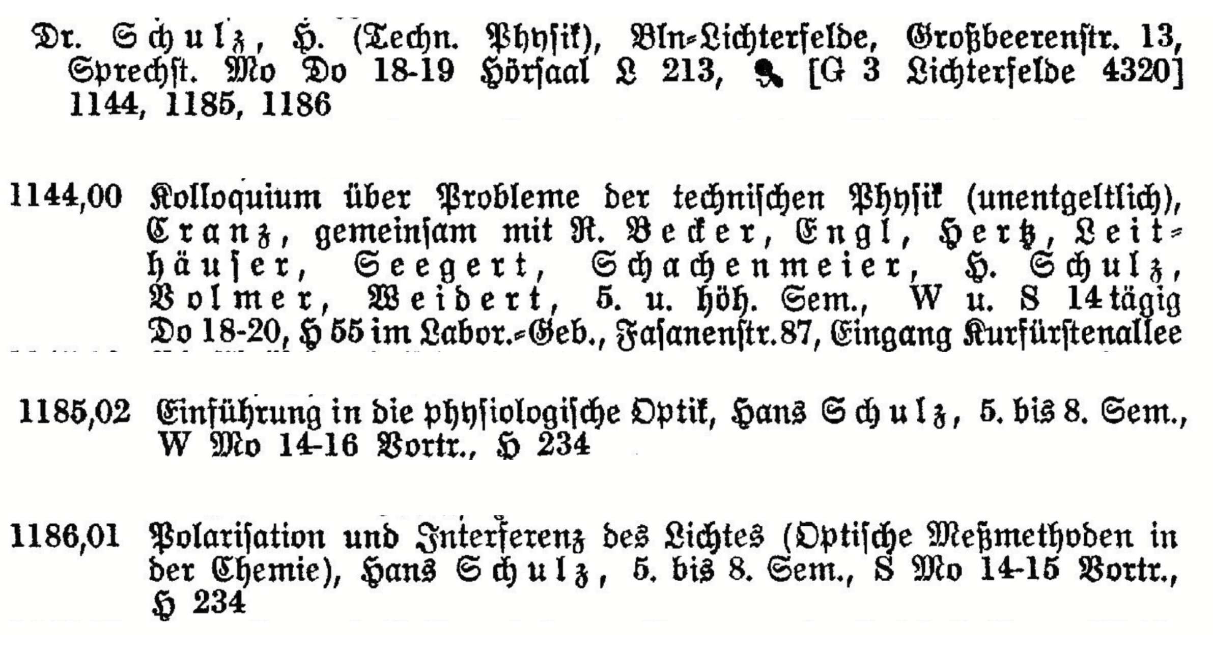
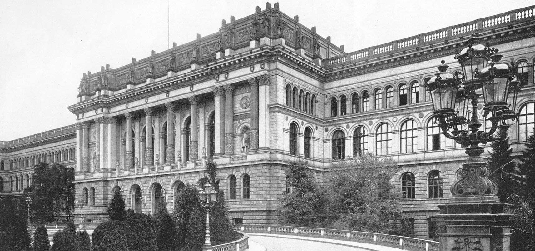
To find the true architect of the Minostigmat, one must leave the glossy world of camera collectors and descend into the dusty catalogs of the Technical University of Berlin, 1934. There, buried among the lists of specialists in applied optics, a name emerges: Prof. Dr. phil. Hans Reinhold Theodor Schulz.
He lived in Berlin-Lichterfelde. He taught physiological optics and the polarization of light. He was the man who understood not just how glass bends light, but how the human eye—and the film—perceives perfection.
The industry giants at Agfa and Leitz had already turned Walter Zapp away, convinced his vision was a technical dead end. They saw a “lemon.” But while the “tenured” elite looked elsewhere, this “non-tenured associate professor” Schulz was navigating a different kind of pressure.
There is no direct evidence available that Hans Schulz was indeed the optics specialist commissioned by Walter Zapp. I have found no unequivocal information on this in the Minox literature or online. The only circulating reference is the aforementioned hint to a “Professor Schulz” who supposedly received this commission in Vienna. All other statements appearing in various places obviously refer to this one source.
As scientific director at the Optische Anstalt C. P. Goerz in Berlin (according to the curriculum vitae of Hans Schulz for his application for the professorship in 1932), Schulz provided the necessary theoretical framework to meet Walter Zapp’s requirements.
Morris Moses describes the evolution of the VEF Minox lens as follows: “After many glass lots had been sampled from Schott in Jena, and consultations had been carried out with Goerz Optical in Berlin, the lens took shape” (Moses, M. (1959). The Minox Story. p. 6). These consultations under Schulz’s guidance could have been the decisive factor in the construction of the Minostigmat.

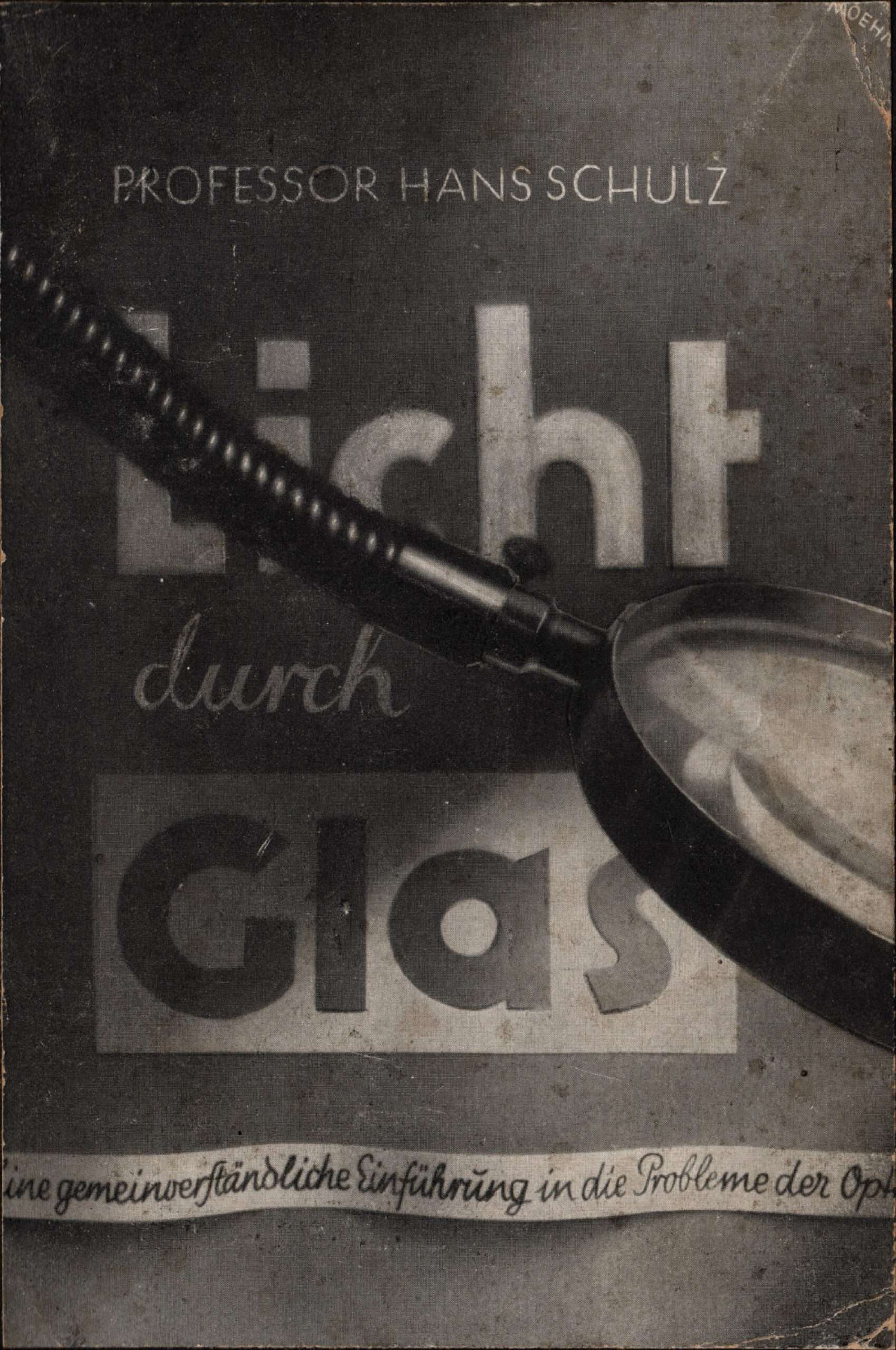
Schulz’ publications, such as Light Through Glass and Seeing, reveal a man who understood how an image must be formed on the retina—and thus on film—to be perfect. While the university was under pressure to conform to the Nazi dictatorship politically, this “non-tenured associate professor” calculated the lens radii that would later make espionage history.
He was the man who made Zapp’s wooden model see. And then, he vanished, leaving behind a legacy that everyone has held in their hands, but whose name almost no one has spoken. Until now.
The Evidence: A Case for Your Judgment
The archives of Minox history contain a curious void. If you look for an official contract or a signed blueprint linking Hans Schulz directly to Walter Zapp, you will find… nothing. The trail in standard literature is frustratingly thin, consistently pointing back to a single, recurring ghost: a “Professor Schulz in Vienna.”
It is a lead that every Minox historian has simply repeated for decades. Yet, as we examine the pieces of this puzzle, a different picture begins to emerge—one that challenges the “Vienna” myth. Consider the following:
- The Academic Trail: While “Professor Schulz in Vienna” remains a spectral figure, Prof. Dr. Hans Schulz in Berlin was a documented titan of applied optics at the very moment the Minox was conceived.
- The Industrial Connection: The development of the Minox lens led directly to the Goerz works in Berlin—the very institution where Hans Schulz served as scientific director.
Is it a mere coincidence that the man who held the keys to Zapp’s problem shared the same name, title, and timeline as the mysterious “Professor from Vienna”? Or was the location simply misremembered in the chaos of a pre-war era, leaving the true architect in the shadows?
I have laid out the traces found so far—from the lecture halls of Berlin to the workshops of Goerz. But the question remains: Is this mere circumstantial evidence, or is there a direct link between this man and the ‘impossible’ Minox lens?
The answer may lie not only in a dusty archive, but in Schulz’s own words. To understand if he was indeed the one who gave the Minox its sight, we must look at a revelation he published in 1940 – a blueprint for a lens that, according to the optical establishment, shouldn’t have existed at all.
Schulz, H.: Light Through Glass – A Popular Introduction to the Problems of Optics, Reinhardt Verlag, Frankfurt am Main, 1940
But before we can look at Schulz’s private records, we must first understand the battlefield on which he fought. To appreciate why the giants of the industry deemed Zapp’s vision ‘impossible,’ one must understand the invisible enemies of any lens: the optical aberrations that haunt every piece of glass. In the following chapters, we will deconstruct the anatomy of a camera lens and the complex problems that Schulz had to conquer.
Only then, equipped with this knowledge, can we return to the man himself—and examine the decisive evidence he left behind in 1940: a blueprint that finally reveals how he tamed the light.
The Minostigmat – Heart of the VEF Minox Riga
In the world of subminiature cameras, the Minox is often regarded as the ultimate. Anyone who takes a look inside immediately realizes that the shutter is the most complex mechanical component in the entire camera. This mechanical masterpiece controls the exposure times with a precision more reminiscent of a Swiss watch than a camera.
The truly critical component, however, is another. With a negative format of just 8 x 11 mm, the lens determines the camera’s usability.
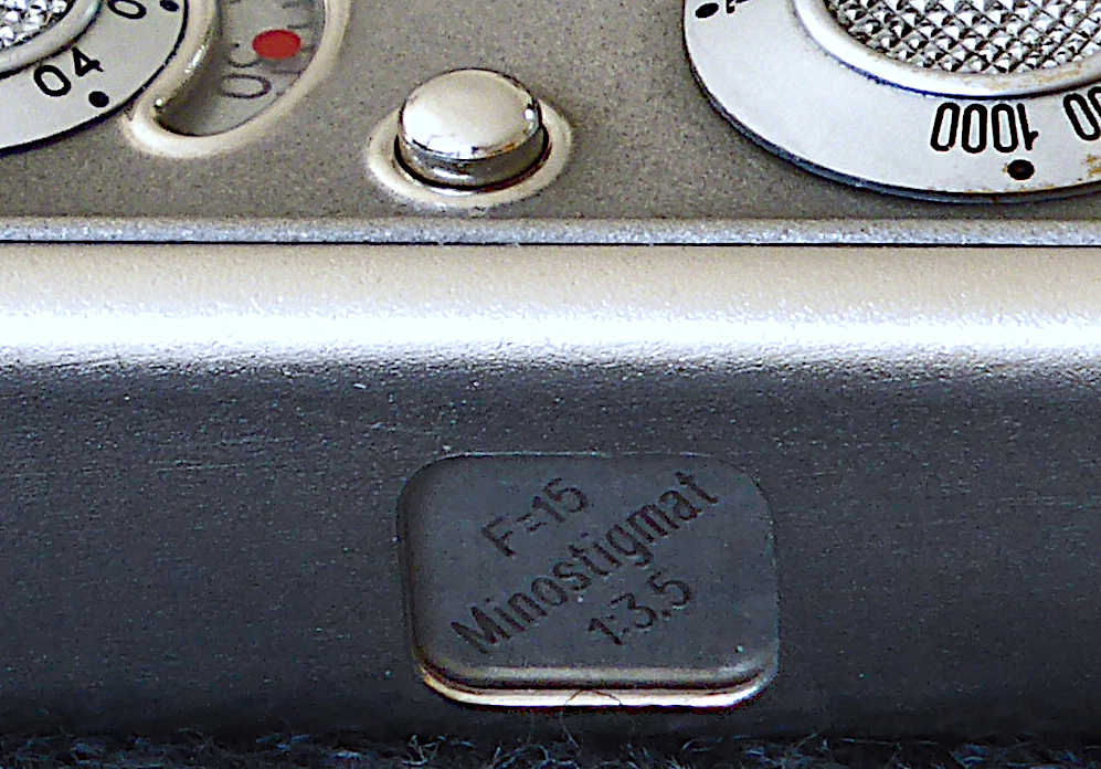
The Riga Minox lens, called Minostigmat, was therefore far more than just a component; it was the Minox’s raison d’être. Only its edge sharpness and light intensity transformed an ingenious mechanical design into a serious photographic instrument.
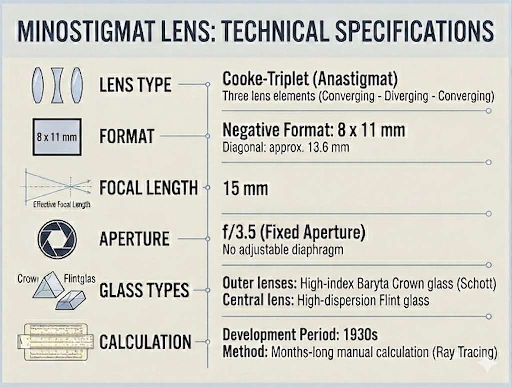
Developing a lens is no easy task, even today. Back in 1935, the Minox lens design faced additional, nearly insurmountable challenges. So let’s start by considering what criteria an outstanding lens had to meet back then. The lens on the Riga Minox is called Minostigmat. The name itself hints at a key feature of this lens: it is an anastigmat.
Challenges for a lens
Why does a camera need a lens?
A camera doesn’t necessarily need a lens. A pinhole camera uses the straight-line propagation of light to create an image. A tiny aperture controls the selection of light rays. This small hole allows only a very narrow beam of light to pass through from each point on an object. This beam strikes the opposite wall, where it creates a small image point.

But pinhole cameras have physical limitations. Since very little light passes through the small hole, extremely long exposure times are required. A lens, on the other hand, allows a much greater amount of light to be captured while still focusing all the rays precisely onto a single point, which enables much brighter images and thus shorter exposure times.
How does a lens work?
A lens makes use of two effects: the refraction of light by glass and the shape of the lens:

- Light travels through the air at nearly the speed of light. As soon as it enters the denser material of glass, its speed is reduced. This sudden loss of speed causes the light beam to change direction—it is refracted. Lenses utilize this effect of directional change.
The so-called refractive index n of a material is derived from the ratio of the speed of light in a vacuum to the speed of light in that material. For optical glasses, it typically ranges from about 1.5 to 1.9. A value of 1.9 thus corresponds to approximately half the speed of light in a vacuum. The refractive index of a material is slightly different for the different colors of light. - Since a lens is not flat like a windowpane but curved, light rays strike its surface at different angles. Common lenses are glass bodies with spherical (ball-shaped) surfaces on both sides, as these surfaces are relatively easy to manufacture. The radii of the two spherical surfaces of a lens can be different.
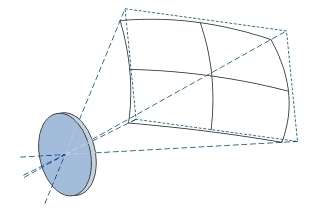
The image above shows, for example, the effect of a glass sphere (a spherical lens) placed in front of a lake and a mountain range. It produces a reduced, laterally reversed, and upside-down image.
In this way, a lens uses its shape and the refractive index of the glass to bend light rays in a specific direction. This creates a reduced image of the object. Since the lens can be much larger than the pinhole in a pinhole camera, the image is much brighter. The focusing effect of the glass surfaces creates an image of the object behind the lens. Here, the light rays emanating from a single point on the object converge and can thus be captured on film.
The problems with a simple lens
A simple converging lens produces various types of aberrations because light rays are refracted differently depending on their wavelength and angle of incidence.
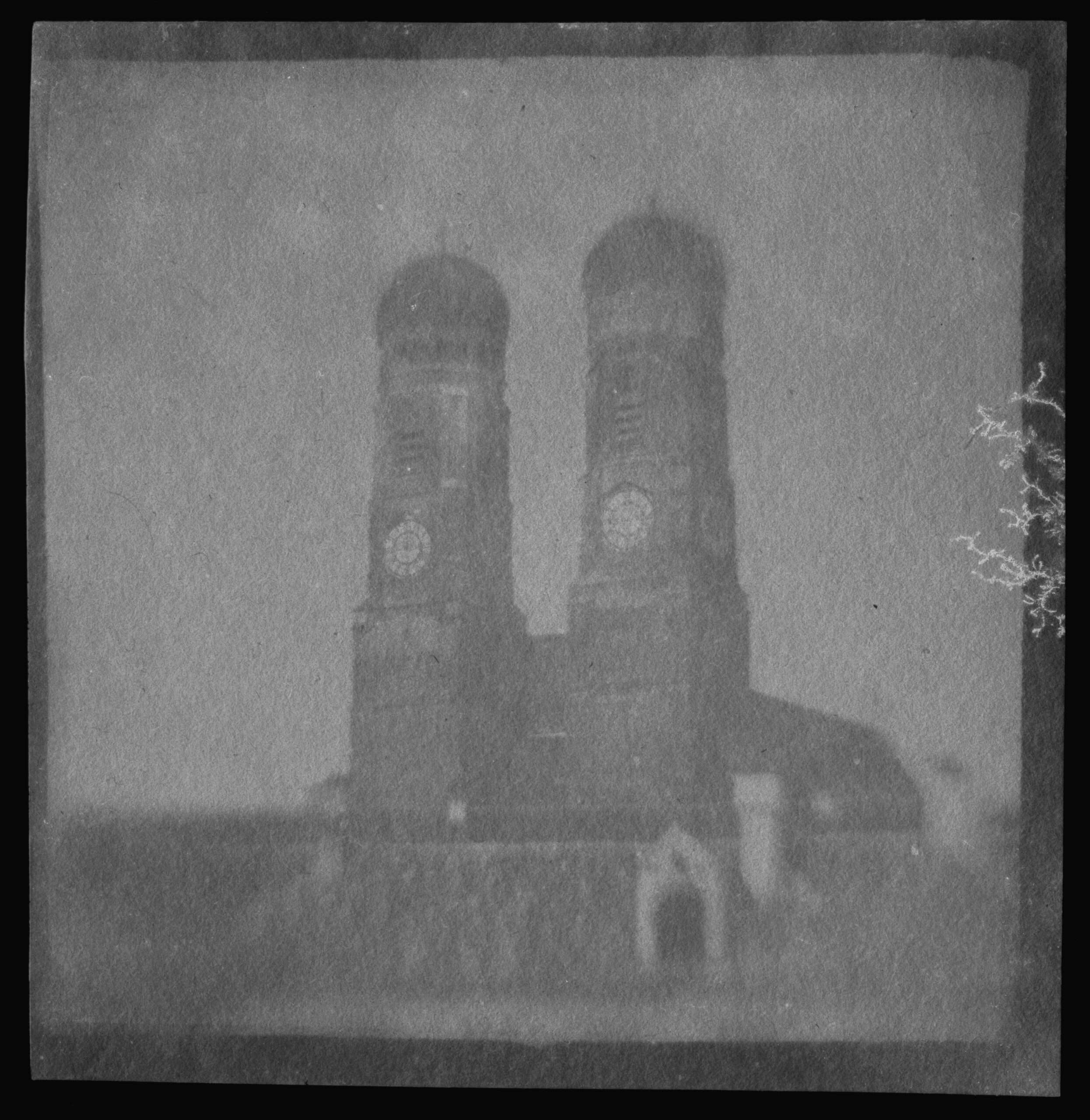
In the 1837 photo of the Munich Frauenkirche by Franz von Kobell, several lens errors in the oldest German photograph are visible. The image was taken with a converging lens (the glass body is thicker in the middle than at the edges). This allows for a much shorter exposure time than with a pinhole camera, but also introduces problems known as lens aberrations:
- The sharpness drops significantly toward the edges. Early lenses projected light onto a curved plane, while the paper negative was flat, causing the center to be in focus while the periphery blurs.
- There is a noticeable darkening toward the corners. The lens design was unable to distribute light evenly across the entire surface.
- The image appears soft and “dreamy” throughout. Rays passing through the edge of the lens didn’t converge at the same point as central rays, resulting in a lack of crisp detail.
- Straight lines, such as the edges of the towers, appear slightly curved or warped because the simple lens distorted the image toward the margins.
- Due to the lack of lens coating, bright areas (the sky) bleed into darker areas (the towers), creating a hazy glow around the silhouettes.
The main reason for these effects is the fact that lenses have spherical surfaces. Furthermore, the index of refraction depends on the wavelength (color). It is also important to keep in mind that these are physical phenomena, not material defects or manufacturing issues.
Here is an overview of the most important aberrations:
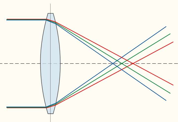
- Chromatic aberration (dispersion):
Since glass refracts light to varying degrees depending on color (wavelength), different focal points are created for different colors. The result is unsightly color fringing along edges.
- Petzval field curvature:
The sharp image does not lie on a plane but on a curved surface. If the center is sharp, the edge is blurry, and vice versa.
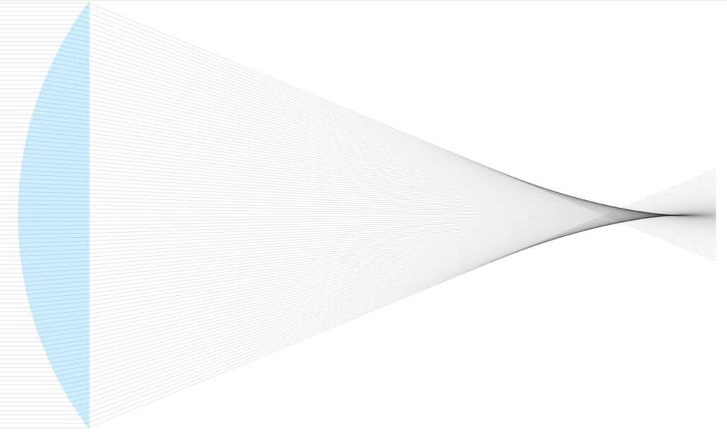
- Spherical aberration:
Rays near the edge are refracted more strongly than rays near the axis. This results in a “focal spot” rather than a sharp focal point. The image appears flat and out of focus.
- Distortion:
Here, in contrast to spherical aberration, we are considering rays originating from objects off-center. The surface of spherical lenses causes a greater deflection of these oblique rays at the edges. This changes the image scale for them. The image is sharp, but distorted. Straight lines at the edge become curves.
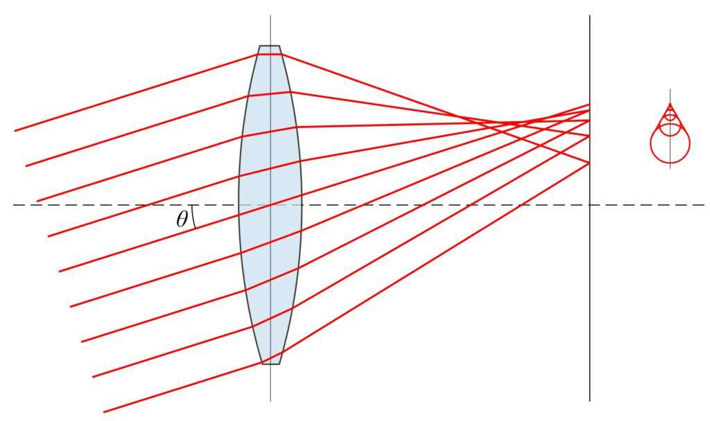
- Coma (asymmetry error):
This error occurs when rays strike the lens at an angle to the optical axis. The light spot becomes distorted and looks like a small comet’s tail.

- Astigmatism (lack of a focal point):
Beams of light entering at an angle are focused to different degrees in the horizontal and vertical planes. Instead of a single point, two spatially separated focal lines are produced.
To minimize these lens aberrations in cameras, lens systems are used. The lens aberration of one lens is intended to be reduced by the lens aberration of another lens.
The design of such a camera lens becomes a mammoth task, known as the “art of lens design,” and can certainly be a lens designer’s life’s work.
Since these optical aberrations are well described elsewhere, I will not go into detail about them here. I would like to limit myself to describing astigmatism, since the name “Minostigmat” of the Riga Minox lens emphasizes the correction of this aberration.
What does an anastigmat do?
An anastigmat is a high-quality photographic lens designed to correct two major optical aberrations simultaneously: astigmatism and field curvature.
Astigmatism is a lens fault that causes a point of the subject to appear as a line on the focal plane. In anastigmatic lenses the fault is corrected by a careful combination of lens elements.
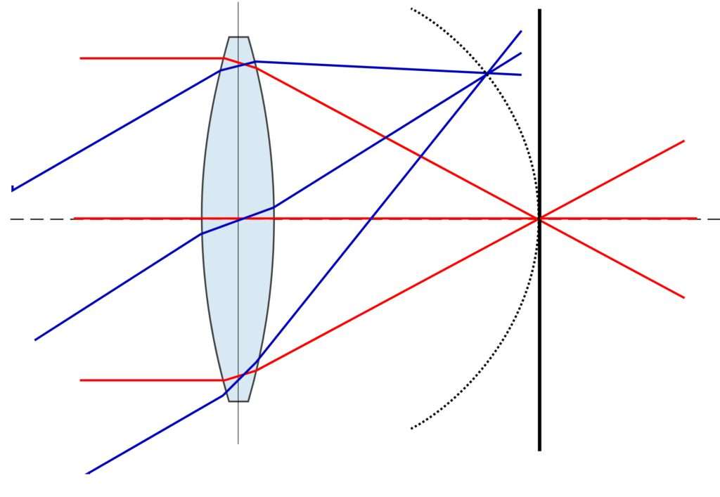
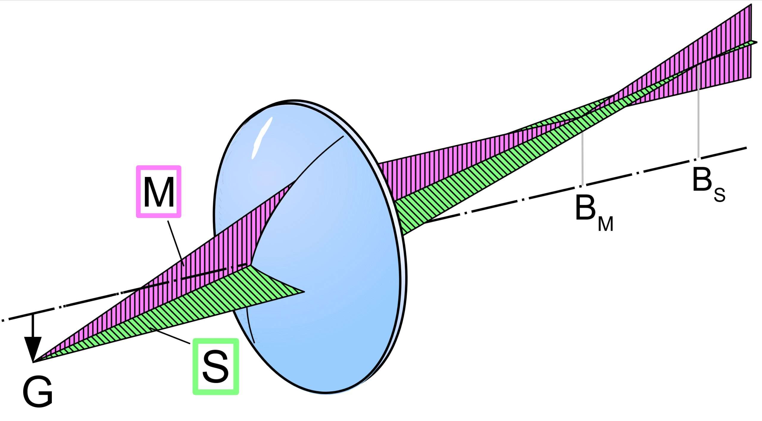
In simple lenses, light rays that strike the lens at an angle to the optical axis are not focused at a single point, but rather at two lines perpendicular to each other. This results in blurriness at the edges of the image. The reason is that rays striking the surface in a vertical plane (the meridian plane) encounter a different curvature of the glass surface than rays striking the surface in a horizontal plane (the sagittal plane). These two specific planes have different focal points; the other planes have focal points in between.
All rays that do not lie on the optical axis (the centerline of the lens) strike the glass at an angle. Thus, rays emanating from point G strike the glass at an angle—some vertically (M, red) and others horizontally (S, green).
Because they strike the lens glass at different, steep angles, the red and green rays have two different focal points, BM and BS. No matter which focal point you choose, some rays will always appear out of focus on the film.
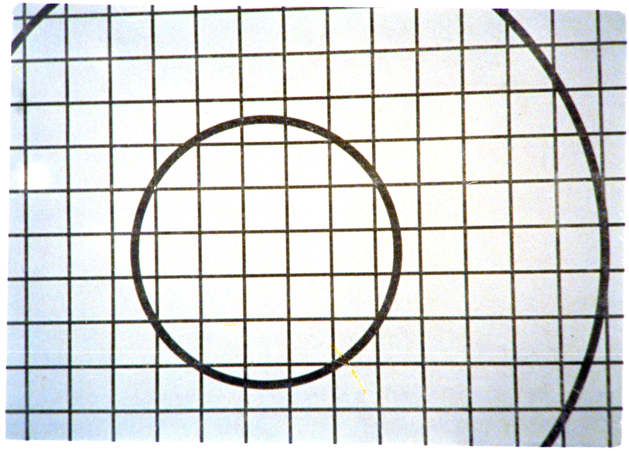
For example, when we photograph a grid (pictures below, far left), a simple lens images the center of the grid differently than the edges.
If we place the image plane (the film) at point BM, we obtain the second picture. In this image, the horizontal lines are sharp. The vertical lines become increasingly blurred toward the sides.
If we place the image plane (the film) at point BS, the opposite is true (picture 4).
Picture 3 shows an image plane located between BM and BS. There, all the image points have a moderate degree of blurriness.
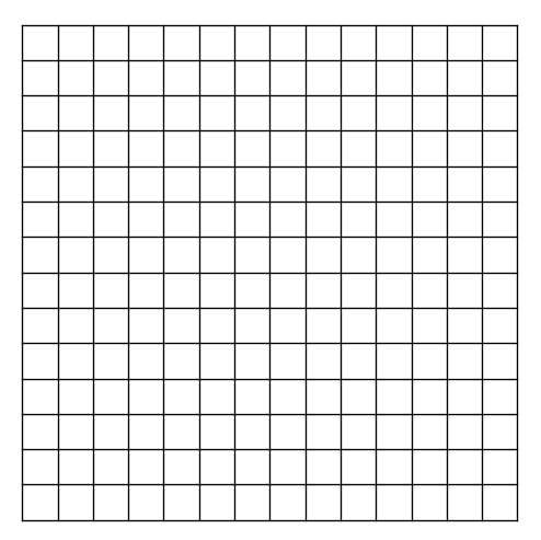

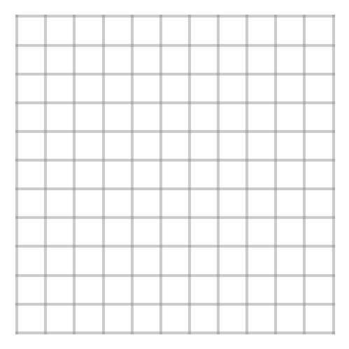
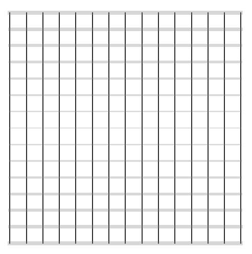
An anastigmat lens corrects this aberration. Appropriately combining several simple lenses, it brings the focal points BM and BS together. In our example, the grid then appears just as sharp on the image plane as it does in object space.
As we will see, designing an anastigmatic lens is by no means a simple task. This is because no formula directly calculates the geometry of the individual lenses for a desired lens design. It requires a great deal of experience and trial and error, combined with an excellent understanding of physical optics.
Hans Schulz – The father of the Minostigmat
In 1935, when building the prototype of his Minox camera, Walter Zapp was frustrated and desperate. Attempts to develop a lens with the assistance of a local precision optician and precision engineers were unsuccessful. The image quality simply would not have been sufficient for the required magnifications. He therefore presumably turned to one of the best German opticians, the physics associate professor Hans Schulz at the Technical University of Berlin.
Who was Hans Schulz?
Schulz (1885–1968) was a German specialist in applied optics and worked closely with the optical industry. For a long time, his books were considered standard works for students and engineers in precision mechanics and optics, for example:
- Schulz, Hans R.: Die optischen Instrumente. Berlin: Springer, 1918 (1. Auflage) / 2. erw. u. verb. Auflage, Berlin/Leipzig: de Gruyter, 1923.
- Schulz, Hans R.: Das Glas. München: J.F. Bergmann, 1923.
- Schulz, Hans R.: Die Polarisationsapparate und ihre Verwendung. Stuttgart: Ferdinand Enke, 1921.
- Schulz, Hans R.: Das Sehen. Eine Einführung in die physiologische Optik. Stuttgart: Ferdinand Enke, 1920.
- Schulz, Hans R.: Licht durch Glas. Eine gemeinverständliche Einführung in die Probleme der Optik. München: Heinrich Reinhardt, 1940.
As we can see from this list, Schulz’s experience and theoretical knowledge made him ideally suited to design this very special lens.
How did Schulz proceed?
Schulz received a specification from Zapp that was actually contradictory: The lens should be tiny, extremely sharp, and have a fast aperture – but it was not allowed to have an adjustable aperture.
Zapp wanted to keep the camera as flat and mechanically simple as possible. Every additional component (such as aperture blades and their mechanism) would have increased the size of the housing and made it more prone to failure.
Schulz worked under enormous physical constraints: the fixed aperture requirement left no room for the usual optical compromises. While designers could normally rely on photographers simply stopping down for critical shots, Schulz had to deliver a lens that always functioned perfectly. He couldn’t hide aberrations behind a smaller aperture. The Minostigmat had to be designed to deliver a resolution at its widest aperture that made enlargements from the tiny 8x11mm negative possible in the first place.
In his book Light Through Glass (1940), he describes the technical and physical considerations that led to his design of the Minostigmat:
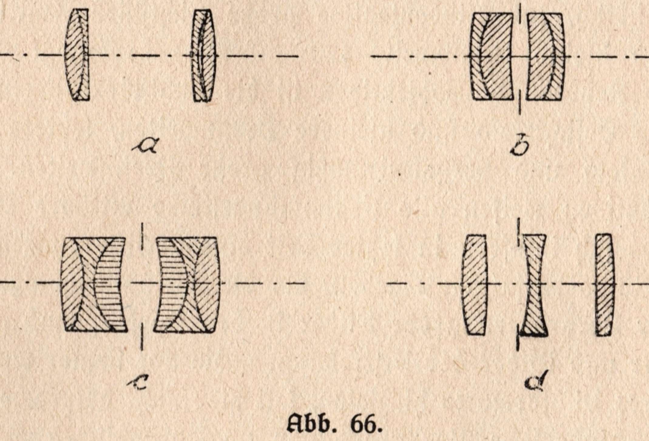
From the immense number of objectives that have entered the market over time, all of which exhibit certain constructional differences, certain basic forms can now be identified, which simultaneously yield an indication of performance capability.
Figure 66a shows the Petzval objective in its basic form, which consists of two achromats following at a certain distance. The focal ratio can be increased up to 1:1.8; the image field is small. In the aplanats and anastigmats shown in b and c, which also consist of two achromats of significantly smaller spacing, the distance (the construction length) is significantly less. At focal ratios of 1:7.7, fields of view of 40–45° could be achieved with aplanats, while with double anastigmats, according to Figure 66c, the aperture can be increased up to approximately 1:3.5 and the field of view up to 65°.
The three-lens Cook objective shown in 66d forms the basic shape for the versatile forms of triplets, in which a non-negligible increase in brightness can be achieved without restricting the field of view. In all forms, however, one observation can be made: objectives of very high speed can only be used for medium fields of view; objectives of medium speed allow an enlargement of the field of view up to 90°, whereby medium speed is designated as that which lies between 1:3.5 and 1:9. A further enlargement of the field of view necessitates a decrease in speed, and if one now also considers the third determining variable of an objective, the focal length, one finds that high speeds are predominantly achieved with medium and smaller focal lengths, and that with large fields of view, the focal length usually becomes quite small.
The selection of the three variables depends on the intended use. For designated portrait objectives, medium speed, a medium field of view, and a large focal length are customary; for cinema objectives, high speed, a medium field of view, and a small focal length (20–50 mm) are preferred; for wide-angles and reproduction objectives, the speed is low; the former have a large field of view and smaller focal lengths, the latter a medium field of view and relatively large focal lengths.
In universal objectives, all determining factors exhibit medium values. To be sure, a certain deviation from this classification method has emerged in recent times, as subminiature photography with subsequent enlargement of the images has moved into the foreground. The pros and cons of these efforts, which aim at ever further reduction of the image format, shall not be discussed here. The initially hindering grain size of the photographic layers has been reduced so far today that one is already in the position to image a newspaper on a few square millimeters in such a way that it is perfectly legible again after enlargement of the image.“
These explanations can be directly interpreted as the theoretical foundation for the development of the Riga Minox Minostigmat lens (1:3.5 / 15 mm). His theoretical descriptions precisely outline the technical challenges he faced in constructing this lens.
Schulz’s concept for the Minox
It is evident from the text above how Schulz approached the task based on his expertise.
- The Cooke Triplet as a Basis: Schulz writes that the three-element Cooke lens is the “basic form for the versatile forms of triplets” and allows an “increase in brightness without restricting the field of view”.
Relationship to the Minostigmat: The Minostigmat is a classic triplet lens. This design was ideal for the Minox camera because, with only three lenses (six glass-air surfaces), it offered enough mathematical freedom to correct the five most important aberrations (the Seidel aberrations) while remaining extremely compact. Schulz used precisely the “brightness increase” mentioned in the text to achieve the fixed aperture of f/3.5 without a stop. - Classification of Aperture (1:3.5): In the text, Schulz defines light intensities between 1:3.5 and 1:9 as “average light intensity” and emphasizes that these allow an “enlargement of the field of view up to 90°”.
Relationship to the Minostigmat: The Minostigmat has a maximum aperture of exactly f/3.5. Why didn’t Schulz go higher (e.g., to f/2.0)? His book provides the answer: With a higher aperture, the image field would have remained small or the depth of field would have been too shallow. Since the Minox has no aperture, he had to choose a value that—as he writes—covered a good depth of field but was bright enough for snapshots. f/3.5 was the “sweet spot” to guarantee sharpness right to the corners of the 8x11mm negative.
- Miniaturization and “Microscopic Images”: Particularly revealing is Schulz’s mention that modern (1940) films allow a newspaper to be reproduced on “a few square millimeters” so that it remains “perfectly legible” after magnification.
Relationship to the Minostigmat: This marks the birth of the Minox as a document camera. To reproduce a newspaper legibly at 8×11 mm, extremely high resolution is required. Schulz describes here, theoretically, precisely what the Minostigmat achieved in practice. He calls these images “microscopic pictures”—a term that perfectly describes Minox photography, as the negative is almost the size of a microscope slide. - Focal Length and Field of View: Schulz notes that with large fields of view, the focal length is usually quite short. He already mentions short focal lengths of 20–50 mm for cinema lenses.
In comparison: The Minostigmat goes even further with a 15 mm focal length. This extremely short focal length was necessary to capture a normal angle of view (corresponding to approximately 45 to 50 mm in 35 mm format) on the tiny negative format. - The Problem of Edge Brightness: In the text, Schulz explains the physical law (the cosine-to-four law) according to which brightness decreases massively towards the edge: With a 60° field of view, the edge points receive “only half as much light as the center”.
Relationship to the Minostigmat: The Minox lens has an angle of view of approximately 48°. According to Schulz, this results in noticeable natural vignetting. Since the Minox lacks an aperture to mitigate this effect by stopping down, Schulz had to calculate the lens curvatures in such a way as to minimize the “intensity reduction” at the edges.
In short, he derived the following basic concept from the task he had received from Zapp:
- He chose the triplet because it is compact and bright.
- He kept the f/3.5 aperture to balance depth of field and wide angle.
- He optimized for maximum resolution to enable “microscopic” document photography.
It seems as if Hans Schulz recorded in his book the physical laws he pushed to their limits five years earlier, making the Minox revolution possible.
Design and calculation of a Cooke triplet
The construction of anastigmats was not new territory at that time. There were already well-known, excellent designs, e.g. the Leitz Anastigmat 1:3.5/50mm from the first production batch of the Leica A model. The particular challenges with the Minostigmat were its tiny size and large fixed aperture of f3.5.
The design of an anastigmat was no longer simply a standard task of geometric optics, but a calculation of the behavior of many individual rays.
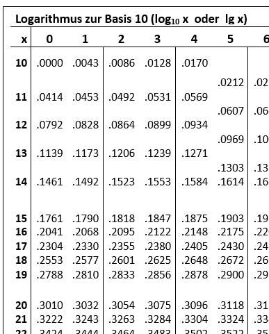
In the 1930s, the calculation process for a lens like the Minostigmat was a months-long, entirely manual process. Since there were no computers, Schulz had to “run” each beam of light through the system step by step using logarithm tables and mechanical slide rules.
The calculation process
Unfortunately, there is no analytical solution that allows you to directly calculate the parameters for a Cooke triplet based on the given specifications. Instead, you have to “guess” a first draft based on experience and intuition:
- Defining the specifications
First, the focal length was determined. A “normal lens” is defined as a lens whose focal length corresponds approximately to the diagonal of the negative format. For 8×11 mm, the diagonal is about 13.6 mm. So a focal length of about 15 mm would have been chosen.
Since the negative is tiny, the resolution must be extremely high, as the images will later be greatly enlarged. The goal would therefore be high sharpness in the center of the image.
At this stage, Schulz established the fundamental parameters:- Focal Length: 15 mm.
- Back Focal Length: The distance from the rear lens element to the film.
- Refractive Powers: How much each of the three individual lenses of the triplet must converge or diverge light to result in a total focal length of 15 mm. During this phase, the distances between the lenses were chosen so that the field curvature (Petzval sum) was already theoretically minimized.
- Selection of glass types
The designer would have consulted the catalogs of manufacturers such as Schott. For a Cooke triplet (three lenses: converging lens – diverging lens – converging lens), the typical choice would have been:
Outer lenses: High-refractive-index crown or barium crown glass (for low aberrations). Central lens: A high-dispersion flint glass (to correct chromatic aberration).
As Schulz describes in his book, the choice of glass is crucial for correcting color errors.- He chose high-refractive Baryta Crown glasses for the two outer converging lenses.
- For the middle diverging lens, he chose a glass with high dispersion (Flint glass). The goal was for the color shift of the negative middle lens to exactly cancel out the color shifts of the positive outer lenses (Achromatism).
- High-index rare-earth glasses, which later became essential for creating extremely compact, high-speed lenses, were not yet in commercial use at that time.
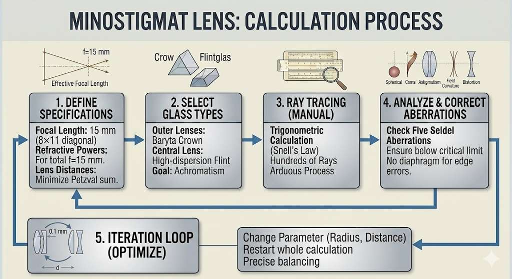
- Ray Tracing (Trigonometric Calculation)
This was the most arduous part. For a large number of light rays (from the center to the edge of the 8×11 mm field), the exact path had to be calculated.- At every glass surface, Snell’s Law was applied.
- A single light ray passing through the six surfaces of a triplet required dozens of calculation steps, which could take hours. Since Schulz wanted to optimize sharpness for “microscopic images” (as mentioned in his book), he had to calculate hundreds of such rays to verify the distribution of sharpness.
- Correction of the Five Seidel Aberrations
After the rays were “traced,” Schulz analyzed the deviations. He had to modify the system so that the following five aberrations fell below a critical limit:- Spherical aberration: Rays at the edge must not have a different focus than rays in the center.
- Coma: light points at the edge must not leave “tails” or smudges.
- Astigmatism: Point-shaped objects must remain point-shaped in the image.
- Field curvature: The image must be sharp on the flat film, not on a curved surface.
- Distortion: Straight lines must remain straight.
- Iteration (Optimization Loop)
If the errors were too large—which was almost always the case on the first try—Schulz had to slightly change a parameter (e.g., increase a lens radius by 0.1 mm or decrease a distance) and start the entire calculation process from the beginning.
The particular difficulty with the Minostigmat was the lack of a diaphragm (aperture). Normally, an optical engineer can “save” a design by stopping it down to cut off edge errors. Schulz had to calculate the lens so that the correction was already perfect at the full aperture of 1:3.5. This required an extremely precise balancing of radii.
Developing a lens—especially for such an extremely small format as 8×11 mm – required a immense feat of calculation. Since computers did not yet exist, everything was calculated by hand using logarithm tables and slide rules.
The following parameters are therefore available at the start of the first review of the draft:
- The different types of glass for the lenses and thus their refractive indices.
- The radii of curvature, the diameter and the thicknesses of the three lenses. Each lens can have different radii on its two sides.
- The distances between the three lenses.
The most time-consuming part was the computational verification of the optics. This required calculating the paths of the light rays through the lenses according to the laws of physics. The results then show whether the triplet lens delivers the desired performance:
Mathematical validation
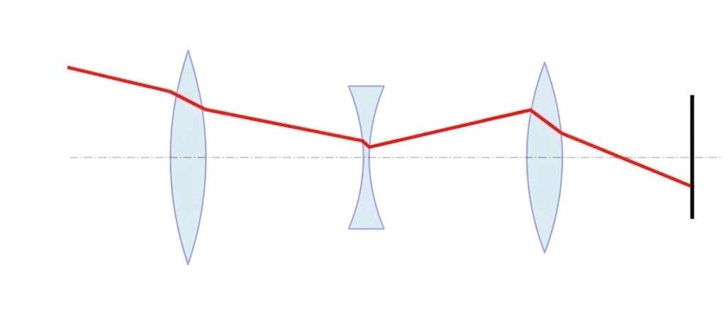
How does one proceed with the mathematical verification of the design? To do this, one imagines light rays passing through the lens system. Using the laws of refraction, the path of the rays can be calculated with the help of geometry. The following diagram shows the geometric relationships for a single light ray as it passes through a lens:
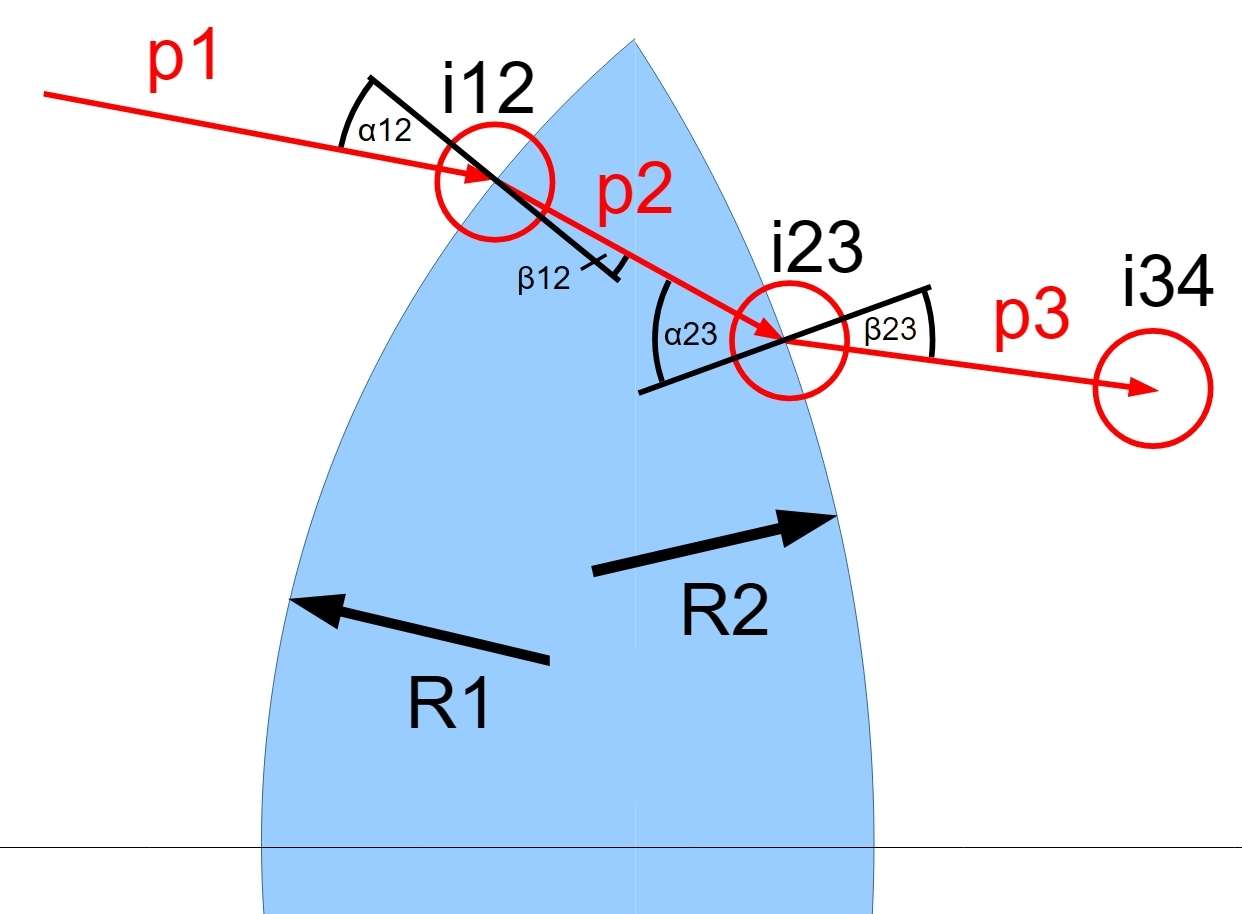
p: paths of ray of light
i: points of impact of the light beam on the lens
α: angle of incidence
β: angle of refraction
R: radii of the lens surfaces
Here is the breakdown of the effort for a single light ray passing through an asymmetric lens (2 surfaces). To carry out multiplication and division, they must be converted into additions and subtractions using logarithms using the rule: log(a * b) = log a + log b.
- Point i12 (Entry point)
- Logarithm Table: approx. 8–10 lookups. One needs logarithms for the squares of the radii, the coefficients of the quadratic equation (A, B, C), and finally for the square root calculation (1/2 * log D).
- Additions/Subtractions: approx. 10 operations (combining the logarithms and working through the quadratic formula).
- Refraction at Surface 1 (Snell’s Law)
At this stage, specialized Logarithmic Sine Tables (log-sin) were often used, which provided the value of log(sin alpha) directly.- Trigonometric Table: 2 lookups (to determine the angle of the normal).
- Log-Sin Table: 3 lookups (log(sin α12), then subtracting log n, then a reverse lookup for α12′).
- Additions/Subtraktionen: 4 operations (angle differences and Snell’s law logarithms).
- Point i23 (Exit point)
This is the most time-consuming part, as it includes the coordinate transformation to the second center of curvature M2 (lens surface with R2).- Logarithm Table: approx. 10 lookups.
- Additions/Subtractions: approx. 12 operations.
- Refraction at Surface 2 & i34
- Trigonometric/Log-Sin Table: 4 lookups.
- Additions/Subtractions: 6 operations.
Entire calculation (p1: i12 -> i23 -> i34) for one ray:
| Tool | Number of Lookups / Operations |
|---|---|
| Logarithm Table | ~25 to 30 times (including Log-Sin and antilog searches) |
| Trigonometric Table | ~6 to 8 times (tan, atan, sin) |
| Additions/Subtractions | ~35 to 45 times |
Total calculation effort for a skilled person
An experienced calculator in an optical factory (who knew the tables almost by heart and had mastered interpolation between table values) would require the following time:
- One beam through one lens
- Pure Calculation Time: approx. 20 to 30 minutes.
- Verification/Safety Check: Since a single error destroys the entire subsequent sequence, a “counter-calculation” or very meticulous record-keeping was usually performed.
- Including documentation, one ray took about 45 minutes in total.
- One beam through three lenses (Cooke triplet)
- 3 x 45 minutes = 135 minutes
- One iteration
To verify the current design of the triplet, 10 to 20 rays need to be calculated. To obtain an image of the lens aberrations with as few rays as possible, the most informative and characteristic rays are selected. We assume an average of 15 ray calculations here.- 15 x 135 minutes = 2015 minutes ≈ 34 hours
- Whole optimization
The optimization can be divided into three phases:- Preliminary phase (rough layout): Creation of the Seidel sums (third order). Approximately 5–10 iterations were performed here to establish the basic framework.
- Main phase (fine correction): Radii and distances were systematically varied. To simultaneously address spherical aberration and longitudinal chromatic aberration, approximately 30–50 iterations were necessary.
- Final phase (zonal correction): Final adjustments for edge sharpness (astigmatism). Often, only specific areas (e.g., only the oblique rays) were analyzed, requiring approximately 20 iterations.
- We can assume that Hans Schulz, as an experienced professional, managed with relatively few iterations; therefore, I’m going with the lower limit.
55 iterations x 34 hours = 1870 hours
Based on a 48-hour work week in the German Reich in 1935 and three assistants for the calculations, the complete optimization of the Cooke triplet for the VEF Minox required:
- 1870 hours / 48 hours/week / 4.33 weeks/month / 3 persons = 3 months
This result would fit with the “grueling wait” of Walter Zapp for the optical data mentioned at the beginning.
Result: The Minostigmat
At the end, Schulz delivered and the design of the Minostigmat design was finally determined.
The design
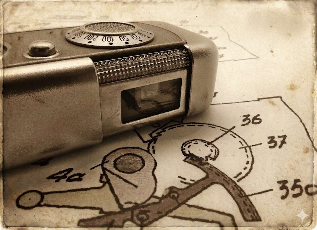
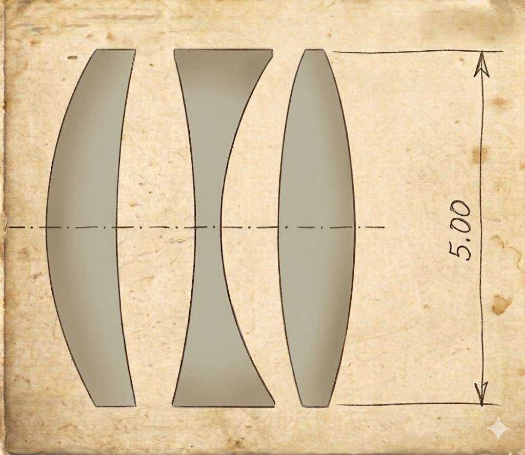
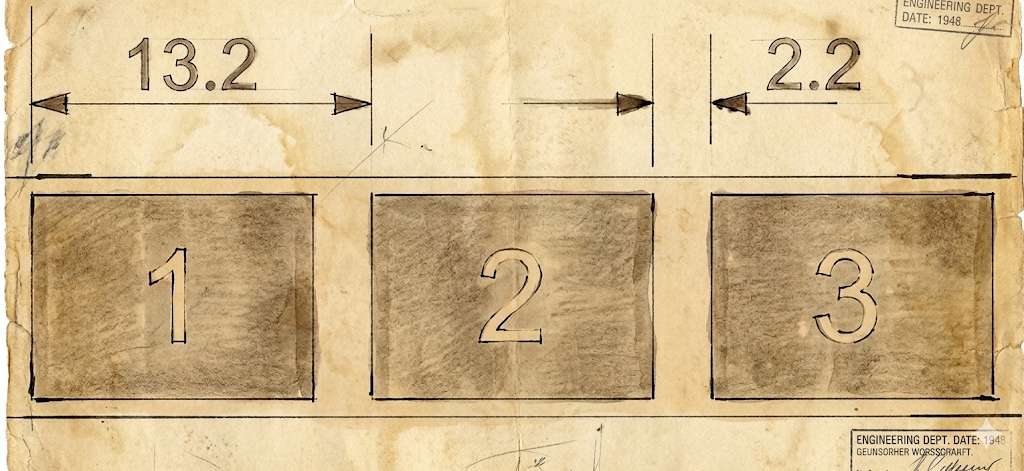
Based on an early technical drawing and measurements of the main dimensions of a real component, I reconstructed the dimensions and distances of the lenses. The following scaled drawing shows the Minostigmat triplet. The front lens is located on the left, with the aperture positioned in front of it. At the time, VEF was likely able to grind the radii to an accuracy of +/- 0.01 mm; therefore, they are given with two decimal places.
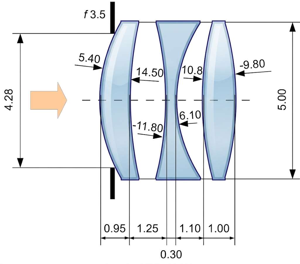
Note that, unlike the standard Cooke triplet design, the front lens has a meniscus shape. A standard triplet usually uses a biconvex front lens. Schulz’s use of a positive meniscus in the Minostigmat is likely due to the following reasons:
- Flat image field: One of the main problems with triplets is field curvature. To project a flat image onto the film, the sum of the refractive powers and radii (the Petzval sum) must be precisely balanced. The meniscus allows the front surface to be more curved and the rear surface to follow moderately, which facilitates the correction of the curvature without worsening chromatic aberration.
- Correction of coma and astigmatism: At an aperture of f/3.5, simple triplets often exhibit edge blurring. The meniscus shape of the front lens helps to focus the oblique light rays more effectively before they reach the negative center lens.
- Length: As shown in the diagram, the entire system is extremely compact: the lens thicknesses and distances add up to only a few millimeters. A meniscus design is optically more compact because the principal planes of the lens can be shifted so that the rear lens can be positioned closer to the film.
Also striking is the thickness of the middle lens, which is technologically borderline. There, the glass is almost as thin as a thick aluminum foil or three sheets of paper.
The following image shows the technical drawing of the lens, presumably from 1935. To the right of it, we see the respective minostigmat produced by VEF:
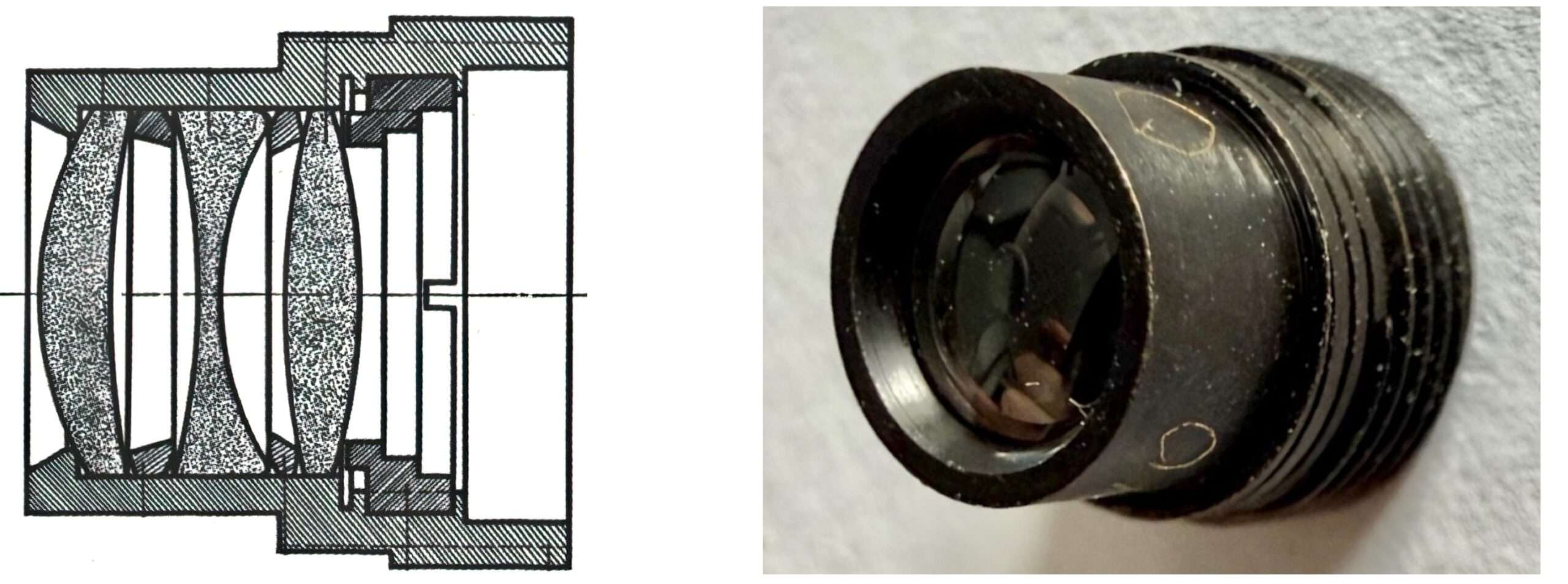
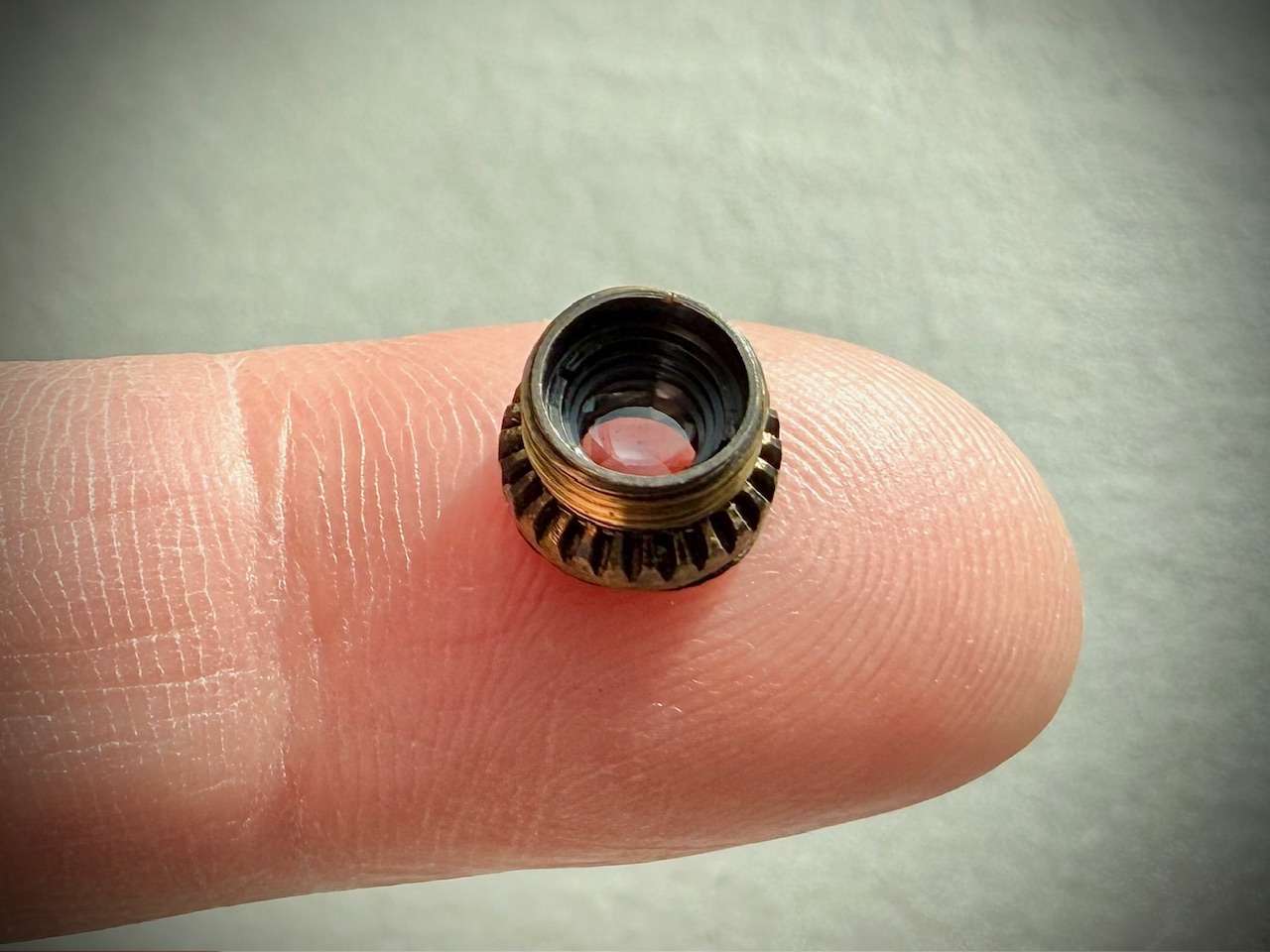
If you only look at the drawings, you can easily forget how tiny the minostigmat is in reality:
The glass
The supplier was the German company Schott (Moses, M.: The Minox Story, p. 6). Based on the lens design, I suspect the following types of glass were used. By pairing specific Crown (SSK4 , outer lenses) and Flint (F2, middle lens) glasses, the designer can control both the path of light and the chromatic aberration. Two properties are important for the glass here: the refractive index and the Abbe number.
The refractive index n is a dimensionless number that describes how fast light travels through a material compared to a vacuum. A higher index means the light is bent more sharply when entering the glass. In this particular design, the two outer lenses probably have a refractive index of 1.617, the middle lens 1.620.
Using a uniform index across different glass types (Crown and Flint) allows the designer to maintain high “bending power” throughout the system without needing extreme lens curvatures. A relatively high index of 1.62 helps in keeping the lenses thinner and the overall objective more compact.
The Abbe number measures the dispersion of a glass – basically, how much the material spreads light into its constituent colors. High Abbe Number (>50) mean low dispersion (the glass doesn’t “spread” colors much). These are called Crown glasses. Low Abbe Number (<50) mean high dispersion (the glass spreads colors significantly). These are called Flint glasses.
With an Abbe number of 55, the outer lenses (SSK4) would provide the necessary magnification with minimal chromatic aberration. The middle lens (F2) would intentionally exhibit high dispersion with an Abbe number of 36.4.
The middle Flint lens acts as a “corrective” element. Because it has much higher dispersion than the outer Crown lenses, its job is to spread the light in the opposite direction. This effectively “collects” the colors back together that were spread by the first lens, resulting in an Achromatic system where different colors of light focus on the same plane.
By keeping the refractive index constant but varying the Abbe number, the designer achieves a sharp, color-corrected image.
Prototyping and Testing
After the calculations, test lenses were ground. Sharpness was checked using test charts, and the design was optimized in an additional round of calculations if the image edges were too blurry.
In a 15-mm lens for 8×11 mm, the lenses are tiny, around 5 mm in diameter. In 1935, mechanical precision was the biggest hurdle. An error of more than 0.01 mm in lens thickness or spacing would have rendered the image unusable at this focal length.
Calculating the focal length
To verify the geometric values of the lenses that I determined, I will now calculate the focal length of this lens system. If the dimensions are correct, the total focal length should be 15 mm, as with the Minostigmat. Here again is the geometry:
1. Definition of lens parameters
The calculation is performed for three thick lenses with refractive indices and .
Lens Geometry:
- Lens 1:
- Lens 2:
- Lens 3:
- Air Gaps:
2. Calculation of individual lens refractive powers (P)
The refractive power of a thick lens is determined by the following formula:
- Lens 1:
- Lens 2:
- Lens 3:
3. Calculation of principal planes (h1, h2)
The position of the principal planes is calculated relative to the vertices S1 (front) and S2(rear).
The individual focal length is: .
Formulas:
(Distance from S1)
(Distance from S2)
Results:
- Lens 1:
- Lens 2:
- Lens 3:
4. Optically effective distances (e)
The distances between the principal planes H’ of one lens and H of the next:
5. System combination (Gullstrand)
Combination of L1 and L2 (P12):
Combination of L1, L2 and L3 (Psys):
Final effective focal length (fsys)
Calculation of the Petzval Sum (P)
The Petzval sum is a primary measure of the inherent field curvature of an optical system. To understand where the formula comes from and how it is applied to the Minostigmat lens, we follow a logical derivation.
1. Derivation of the Formula
The Petzval sum P for a system of lenses is defined by the sum of the reciprocal products of the refractive index n and the focal length f of each element:
To express this in terms of the physical lens radii (R), we substitute the Lensmaker’s Equation for a thin lens:
By inserting the Lensmaker’s Equation into the Petzval definition, we get:
2. Parameters and application
For our specific Triplet design, the total Petzval sum is the addition of the individual contributions:
Given Data:
- Lens 1:
- Lens 2:
- Lens 3:
3. Step-by-Step Calculation
Lens 1 (Positive outer lens):
Lens 2 (Negative inner lens):
Lens 3 (Positive outer lens):
Final Result
Evaluation and contextualization
Why P = 0.0234 an excellent result is:
- Correction Level: A standard single lens of the same focal length would yield a Petzval sum of approx. 0.0412. This design cuts the field curvature nearly in half.
- The Anastigmatic Ratio: With a total optical power K = 0.0667 (for f = 15mm), the ratio P/K is 0.35. In high-end optical design, a ratio between 0.25 and 0.40 is considered “well-corrected,” balancing field flatness with the correction of other aberrations like astigmatism.
Evaluation
The computational verification of the lens geometry shows that the geometric values presented above (radii of curvature, air gaps and lens thicknesses) as well as the assumed glass types (refractive indices) are correct. They also show that the lens is very well optimized with regard to field curvature.
The Minostigmat wasn’t just a small lens; it was a mathematically dense lens. By using the high-index SSK4 glass and a non-traditional meniscus orientation, Schulz balanced five major optical errors in a length less than 8 mm long.
The resulting 15.0mm focal length and the near-zero Petzval Sum allowed the Minox to capture images that could be enlarged to 13×18 cm – a feat previously thought impossible for subminiature cameras.
Conclusion
With the Minostigmat Hans R. Schulz created an optical masterpiece in a tiny space using only three lenses. His knowledge as one of the most respected physicists in the field of optics of his time, as well as his practical experience, were the prerequisites for this.
The stakes for the Minox were high. In the 1930s, subminiature cameras were often dismissed as mere toys. Had Schulz’s lens delivered less results, the VEF Minox would have flopped upon its release. It was the breathtaking image quality – allowing for sharp enlargements from a tiny 8x11mm frame – combined with the surprising robustness of the camera’s internal construction that turned it into a professional tool.
Without this initial proof of concept, there would have been no reason for post-war investors to put money into the brand. The technical brilliance of the Riga model ensured the survival of the system; it provided the commercial and reputational foundation for the next 60 years of Minox history. Moreover, my comparison has shown that the lens can absolutely hold its own in practical use against the Complan lens of the subsequent Minox generation. See my review here.
Hans Schulz died on July 17, 1968, at the age of 83 in Hilterfingen, Switzerland. His wife Elisabeth, to whom he had been married in 1909 and with whom he had four children, had died three years earlier.
Minostigmat test photos
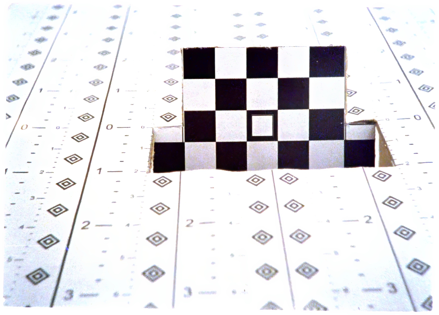
Here are some test photos, I have taken with the Minostigmat (click to enlarge):
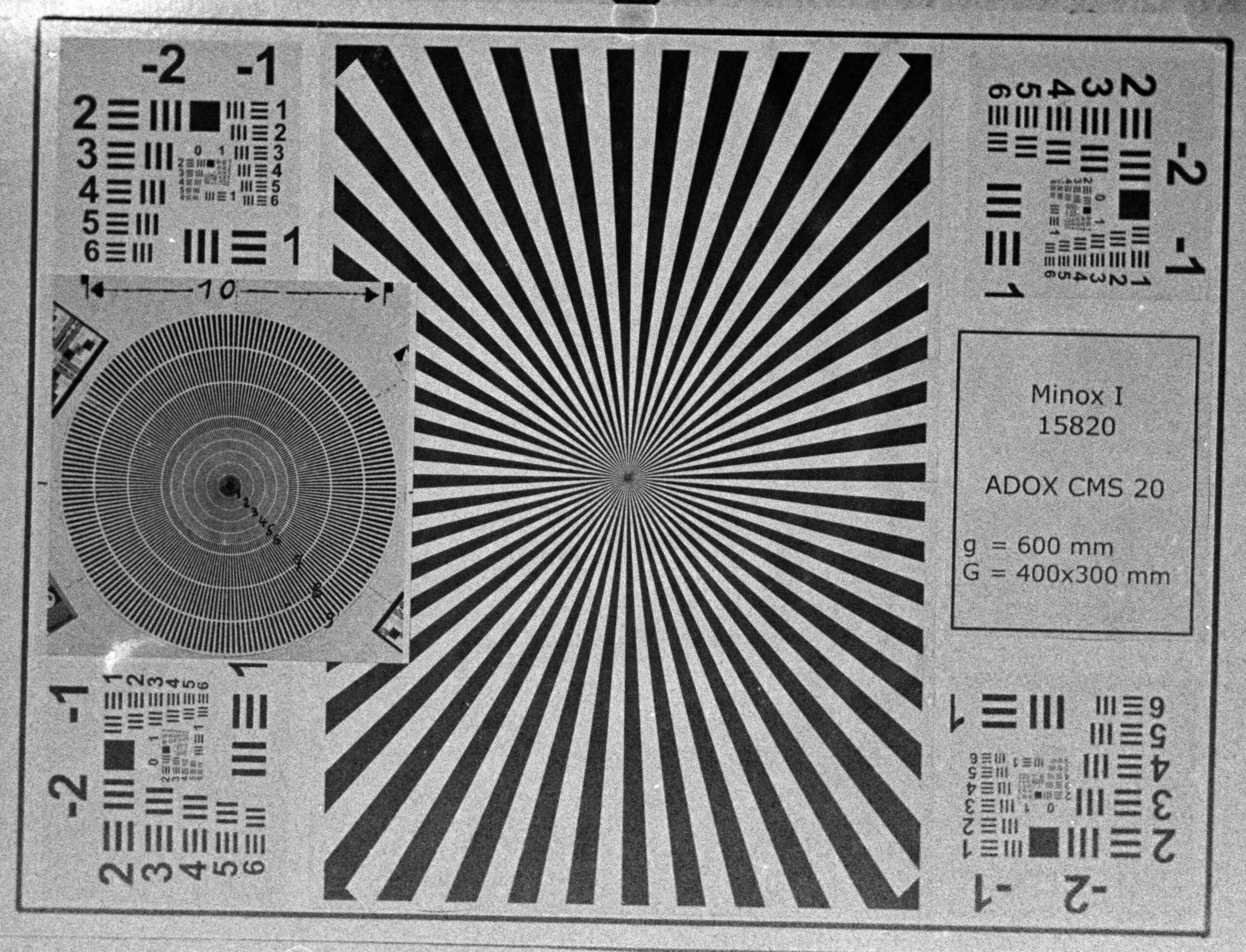
Riga Minox, Adox CMS 20 II


More information about the VEF Minox Riga
You can find more information about the VEF Minox Riga camera here:
- A comparison between the Minostigmat and Complan lenses of later Minox models can be found here.
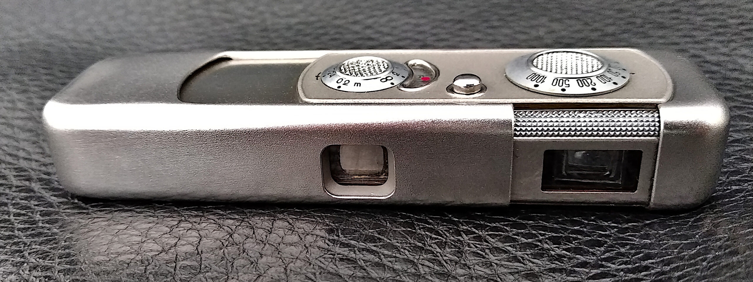
- Here I present my own VEF Minox Riga and its design principles.
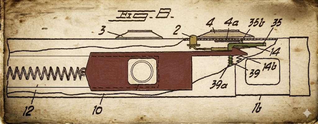
- How the VEF Minox Riga shutter works: A detailed explanation of this shutter, which differs fundamentally from all subsequent Minox models.
- Restoration of a VEF Minox Riga: A unique description of a repair project with unique pictures and video of the inner workings of this camera.