The Minox shutter speed dial is, alongside the shutter release button, the second user interface of the exposure system. It controls the internal shutter mechanism and thus determines the duration during which the shutter blades remain open to expose the film. How to determine the required exposure time for a Minox is not the subject of my consideration here. I have explained this in detail here.
So the question here is how the blade control subsystem mechanically controls the shutter blades based on the position of the shutter speed dial wheel in order to achieve the specified exposure time.
Page Contents
Transfering the presets
The transmission of user input must be purely analog and even purely mechanical. Added to this is the extreme lack of space. It is therefore an extraordinary design achievement to accommodate such a wide range of shutter speeds—1/2 s to 1/1000 s—in such a small space. No other mechanical subminiature camera has achieved this. Even a Leica (which is eight times larger!) from that period requires two shutter mechanisms, one for short exposure times and one for longer than 1/20 s exposure times.
The user interface
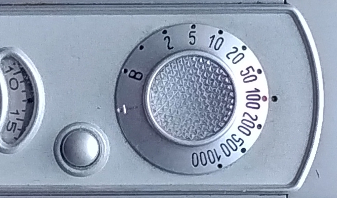
The Minox user interface is extremely clear, as is the shutter speed setting. It also doesn’t matter when you make the setting—before or after cocking.
A rotational movement of the dial takes place, and the blade control system has to evaluate its position.
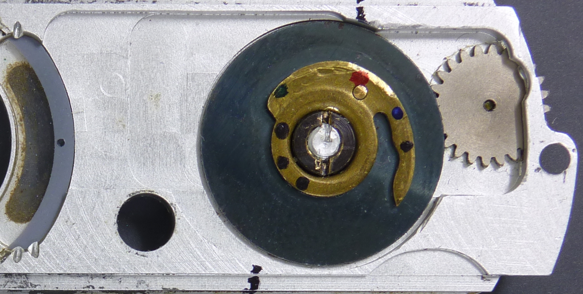
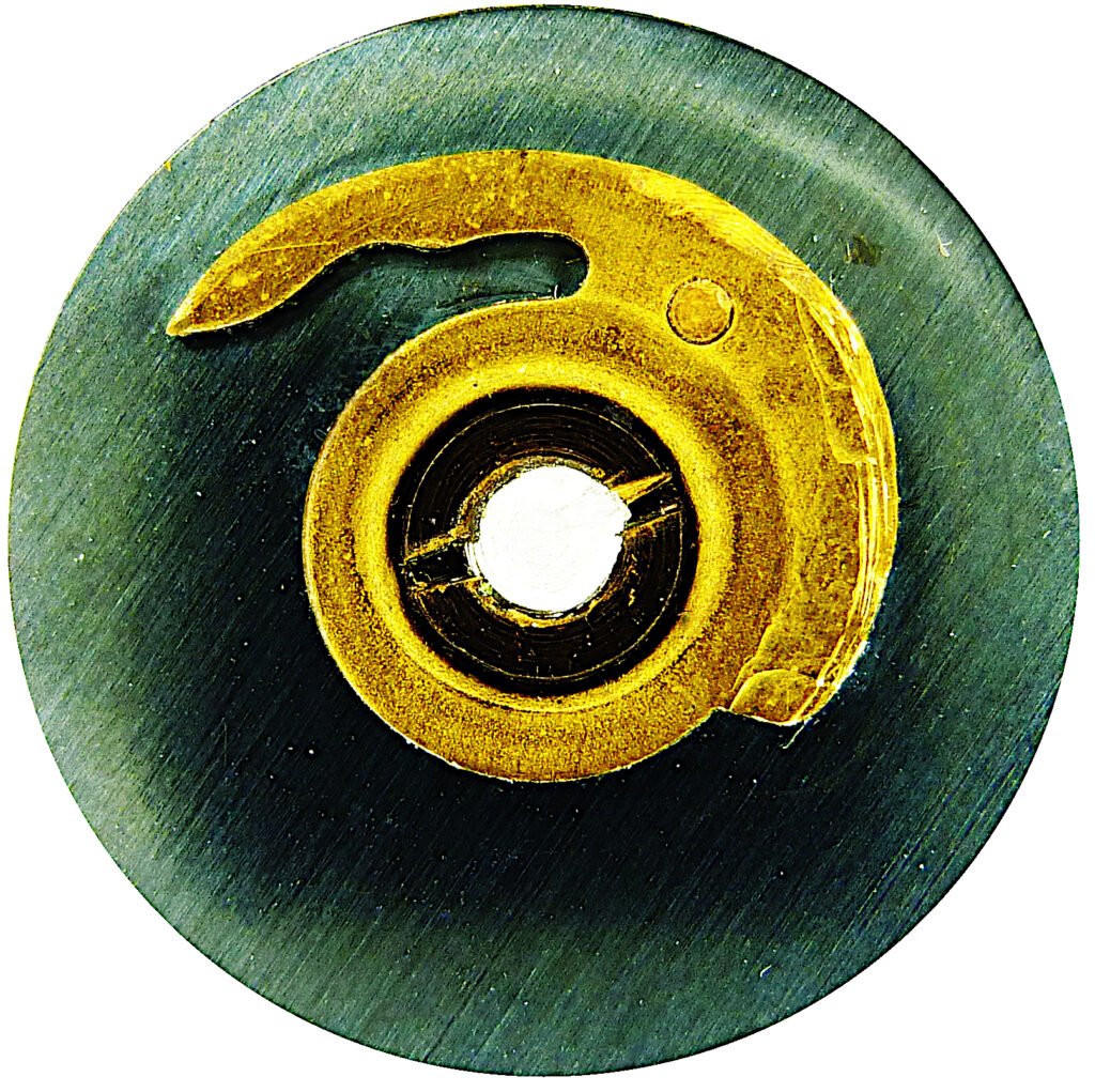
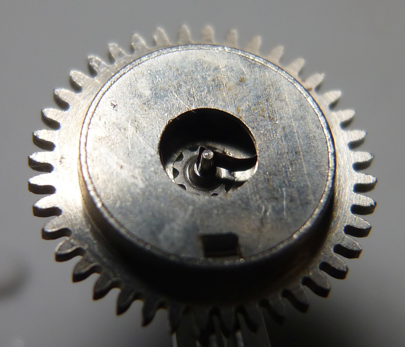
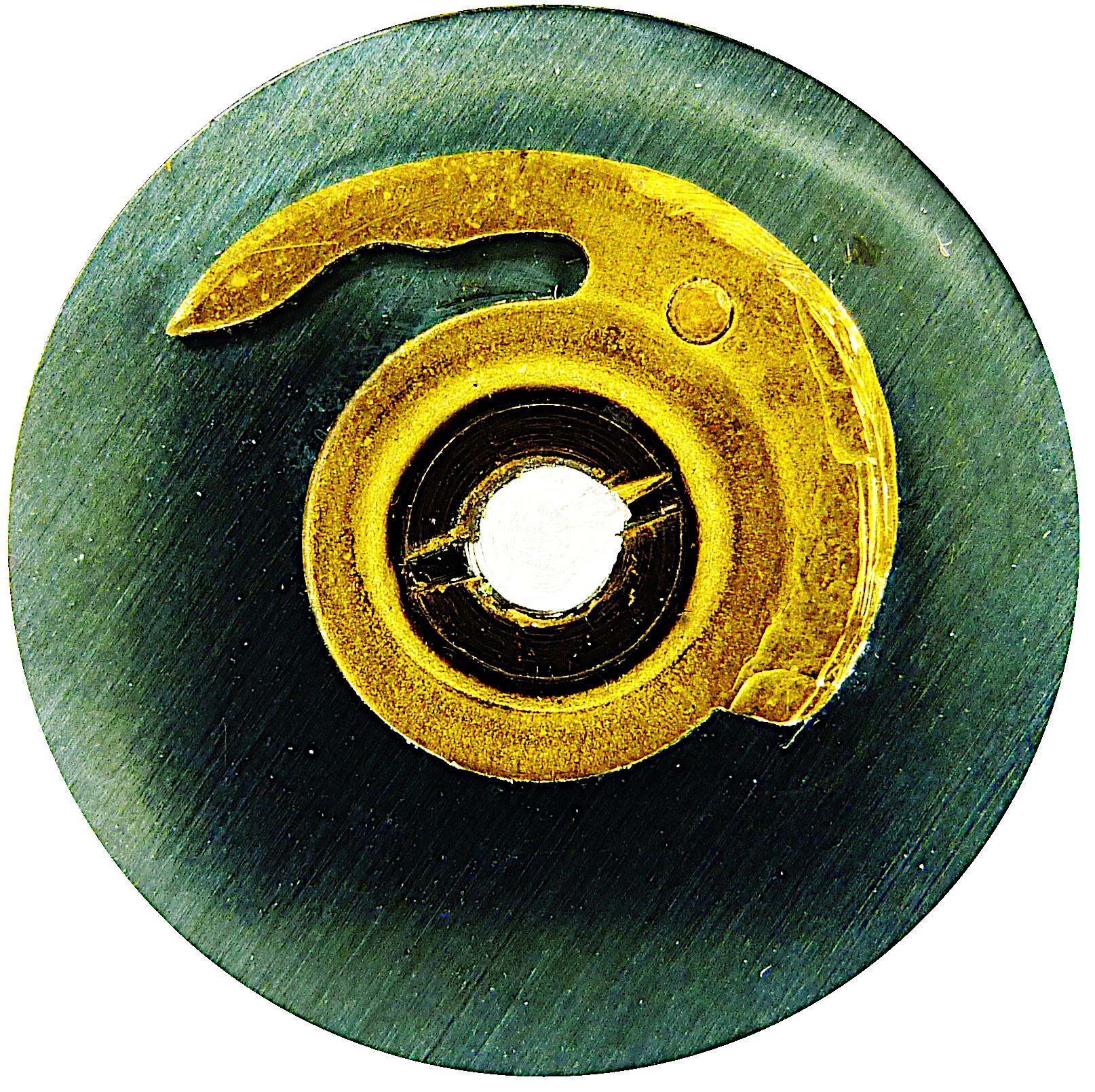
Let’s take a look at the shutter speed dial from below. We see a cam disc that is firmly connected to the dial and therefore rotates with it.
We see a rotation position shown here with the shutter speed set to 1/100 s, as in the image above.
Transferring the setting of the Minox shutter speed dial
Let’s take a closer look at the shape of the cam.
Half of the cam disc, the left side, has a constant diameter on the outside. This is the range for “T”, “B” and 1/2 s. The other half has a spiral shape on the outside. This is the range from 1/5 s to 1/1000 s. The following image shows the cam disc as if you were looking through the front panel from the outside:
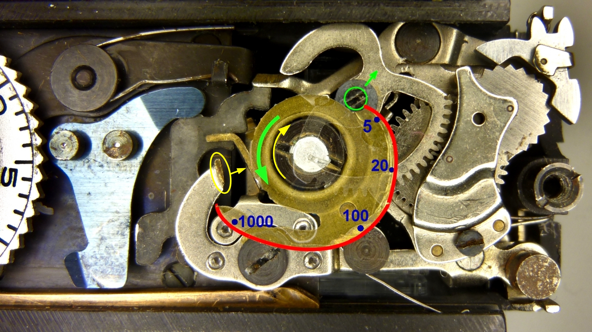
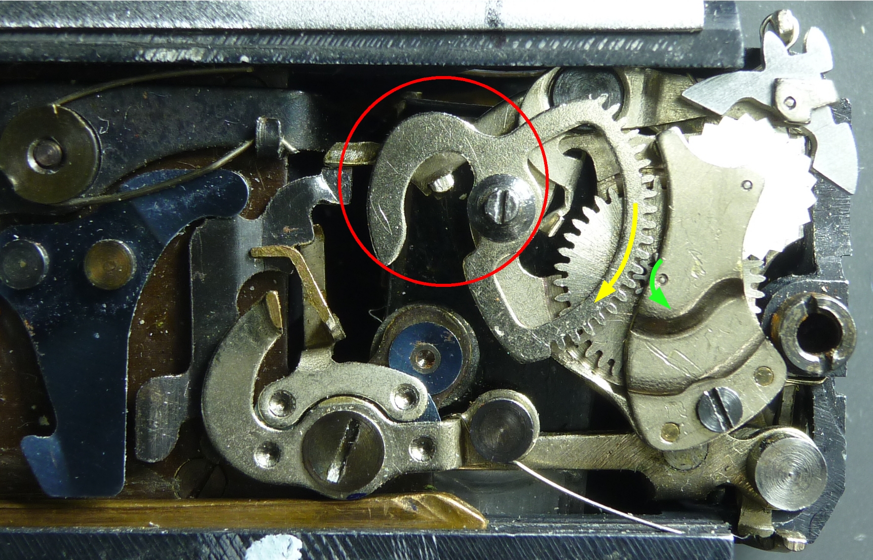
Direction of rotation green: shorter times, yellow: long exposures “B” and “T”
The decisive factor is the pin of the segment gear (green circle), which presses against the cam disc with spring force. When it is moved in the direction of the green arrow, the starting position of the escapement changes to shorter exposure times (red line). This is achieved by the spiral shape of the cam disc.
You may be wondering why the cam disc is hook-shaped in the 1/1000s and 1/500 s range. The hook is used during the “T” and “B” times to move the pin (yellow circle) of the long exposure lever in the direction of the yellow arrow.
In the following sequence of images, we see the positions of the cam disc and the two pins for selected exposure times. The pin for the escapement is shown in green, the pin for the long exposure mechanism in yellow:
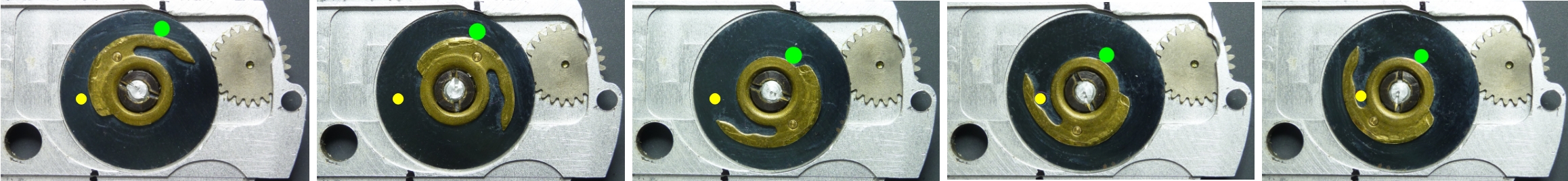
The adjustment range
It is amazing how short the path of the green dot in the image above is when you alter the speeds. Nevertheless, the escapement must be shifted in this manner across the entire shutter speed range. I therefore measured the radius of the spiral for 1/5 s and for 1/1000 s:
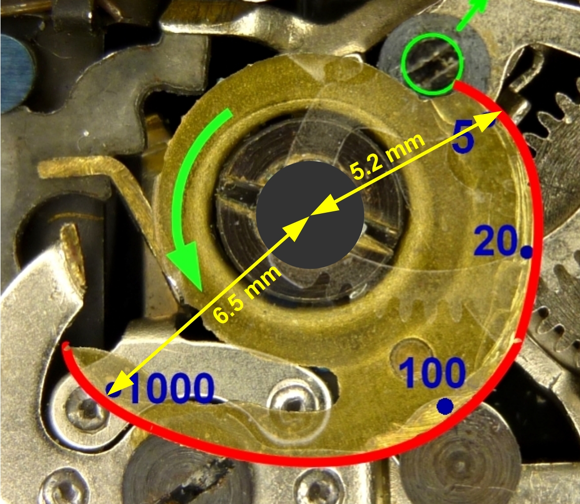
The maximum difference is just 6.5 mm – 5.2 mm = 1.3 mm. This shift of the escapement is sufficient to achieve all shutter speeds from 1/5 s to 1/1000 s!
Swiveling the escapement
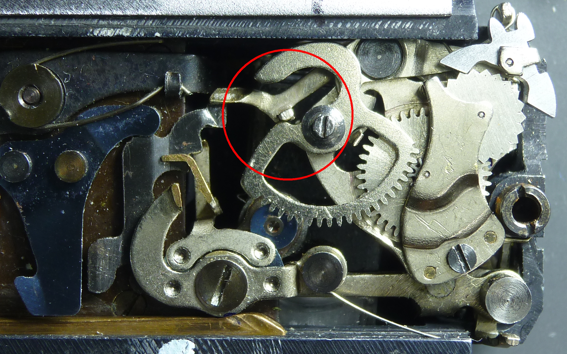
The question now is how moving segment gear center (green circle) affects the escapement. Let’s look at the following image. It shows the direction (green arrow) in which the center point of segment gear 3b moves:
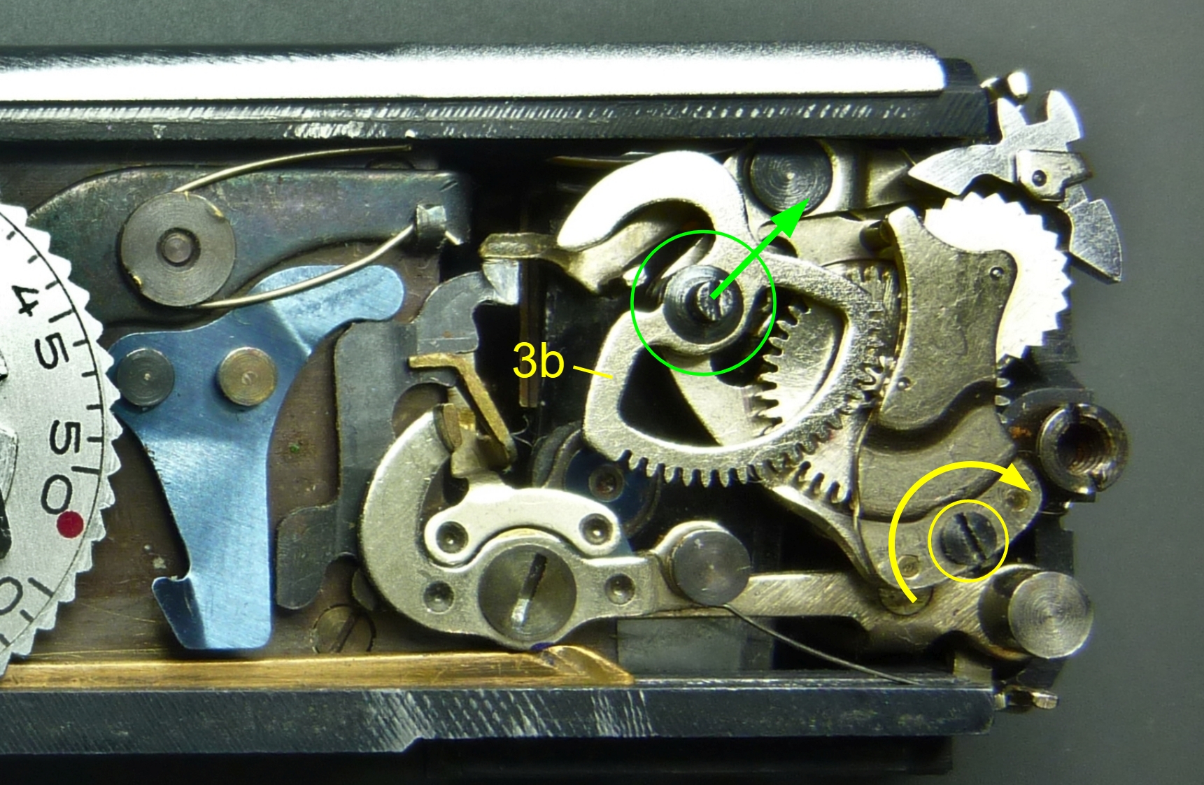
The escapement is mounted in the yellow-rimmed screw so that it can rotate. It will therefore rotate as a whole in the direction of the yellow arrow.
The starting position
What follows now is the most difficult part to understand. Several components move in a complicated manner. But don’t worry, in the next chapter we will see what happens with the help of pictures and videos. If you don’t understand the following lines when you first read them, don’t be frustrated. It took me more than a year to understand these concepts.
The task of the barrel spring
The escapement has a very small and not particularly strong torsion spring inside the barrel, which drives the central pinion counterclockwise. The spring force is calculated so that it cannot counteract the counterforce of the escapement lever once the release button is pressed.
However, if the escapement lever does not press against the segment gear, the barrel spring ensures that the pinion turns the segment gear clockwise until the pin of the escapement lever strikes the segment gear. Where this contact occurs depends on the position of the screw pin of the segment gear and thus on the rotational position of the shutter speed dial cam.
In short, the torsion spring inside the escapement ensures that the segment gear always fits snugly against the pin of the escapement lever. This is the desired starting position of the escapement for the set exposure time. The following two images illustrate the processfor a preset 1/2 s:
In reality, this process is continuous. As soon as the pin detaches from the segment gear during cocking, the segment gear follows it. In this way, the pin and segment gear remain in contact during the cocking process.
The end stop
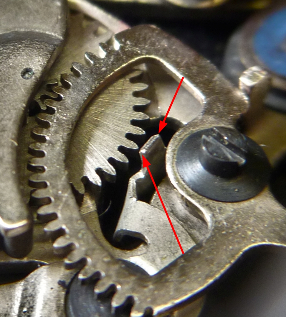
To prevent the teeth of the pinion from disengaging from those of the segment gear, there is an end stop that prevents this in both directions, see image on the right.
The end stop is a curved piece of metal that is firmly connected to the escapement housing and swivels with it.
The moment it happens
The process of joining the segment gear and lever pin takes place when the shutter is cocked, because only then can the segment gear move freely. So when a photo is taken and the shutter is cocked again, the segment gear follows the lever pin to its starting position. However, there is a second situation in which this must happen. If the exposure time is changed, i.e. the shutter speed dial is turned, while the shutter is cocked the segment gear must also turn to the new starting position.
This operation can be clearly heard from the outside as a buzzing sound, at least with long exposure times. Try it! For example, if you cock the shutter after releasing it at 1/2 s, or if you change the time with the shutter cocked. The buzzing sound comes from the oscillating anchor of the escapement.
Triggering
Now let’s take a look at the result achieved by different starting positions of the escapement.
Starting position
To see the effect of the shutter release button’s starting position, I selected the two most different exposure times offered by the Minox spy camera. These are the longest at 1/2 s and the shortest at 1/1000 s. One is 1/2 s, the other is 1/1000 s preset. With the shutter cocked (grey circles), the two situations are as follows:
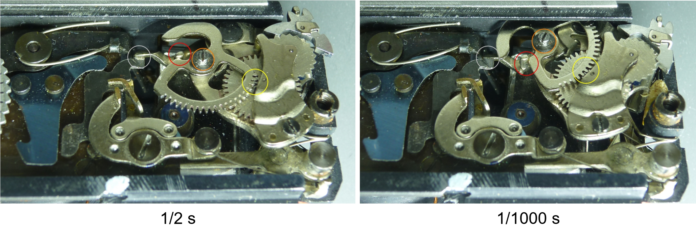
Let’s first compare the position of the screw pin of the segment gear (orange circles). The different positions are caused by the speed dial cam, which has moved this pin there. Also note how, at 1/1000s, the entire escapement has rotated to the right around its mounting screw (front left).
Next, let’s look at the tooth engagement between the central wheel of the escapement and the segment gear (yellow circles). We can see how the barrel spring has turned the segment gear into very different positions in both cases via the central wheel. On the left (at 1/2 s), it has turned the segment gear clockwise to the extreme position. On the right (at 1/1000 s), the segment gear has turned counterclockwise to the opposite extreme position.
Trigger is pulled
As a result, we now see the pin of the escapement lever (red circles) in two completely different starting positions. On the left, after being triggered, the pin has to travel a long way, pressing against the edge of the segment gear and thus driving the escapement. This means that it takes 1/2 second to reach the end stop. We can see this process in the following video:
At 1/1000 s, it’s completely different. The pin of the escapement lever simply slides past the side of the segment gear and can run unchecked toward the end stop the entire time. This takes about 1/1000 s. In the following video, we can immediately see the difference:
All other exposure times are executed according to the positions corresponding to the respective time, which lie between the two shown above.
The 1/1000 s is a special case in that the timing mechanism is practically bypassed here. For this reason, the 1/1000 s often works even on cameras where the other times are quite inaccurate.
Conclusion
We now understand what happens inside a mechanical Minox spy camera when the user selects an exposure time.
The length of the braked movement of the two blade control levers is set via a cam disc at the underside of the shutter speed dial. It is done by the contour of a segment gear, which the lever presses around. The movement of the blade control lever is braked by the escapement over a certain distance. The length of the distance corresponds to the preset shutter speed.
At speeds ranging from 1/2 s to 1/500 s, the movement of the blade control system is slowed down by the escapement mechanism. The speed to which the blade control is slowed down is always the same.
At 1/1000 s, the blade control moves in exactly the same way, but without any braking.
At the manual speeds “B” and “T,” the same process occurs as at 1/2 s, but the process is stopped shortly after the lens is opened. After releasing (‘B’) or pressing (“T”) the release button again, the blade control goes through the 1/2 s sequence and then closes the lens. This is why the lens does not close immediately, but only after a short delay.
Go to the next article The trigger mechanism
Back to the article The minox exposure system