
The shutter release button has been pressed and the timing mechanism generates the correct times for opening and closing the shutter based on the preset shutter speed. This information must now be converted into a mechanical movement that first triggers the opening blade and then the closing blade. This is precisely the task of the blade control subsystem.
This article shows for the first time how the shutter control works on the mechanical 8×11 Minox models. The images provide previously unknown insights that cannot be obtained without destroying the camera.
Page Contents
Connection escapement – blade control
For a long time, I wondered how the connection between the shutter mechanism and the blade locking arm was constructed. This was compounded by the question of how the shutter control was actually driven. Both are so deeply hidden inside the Minox that it is impossible to find answers to these questions without destroying at least one camera. In this case, it is the escapement that prevents us from seeing how everything fits together. The escapement cannot be removed from the Minox without the spring barrel popping out of its mounting. In my experience, this cannot be repaired. In order to take the following photos, the escapement lever also had to be separated from the escapement housing. This is also irreversible. After that, however, everything became clear and easy to understand.
In addition to the questions mentioned above, there is also the aspect of repairing and adjusting the shutter speeds. In order to know where, what, and how to clean and/or lubricate, you need to understand the mechanical processes involved; otherwise, you’re just poking around in the dark.
The missing link
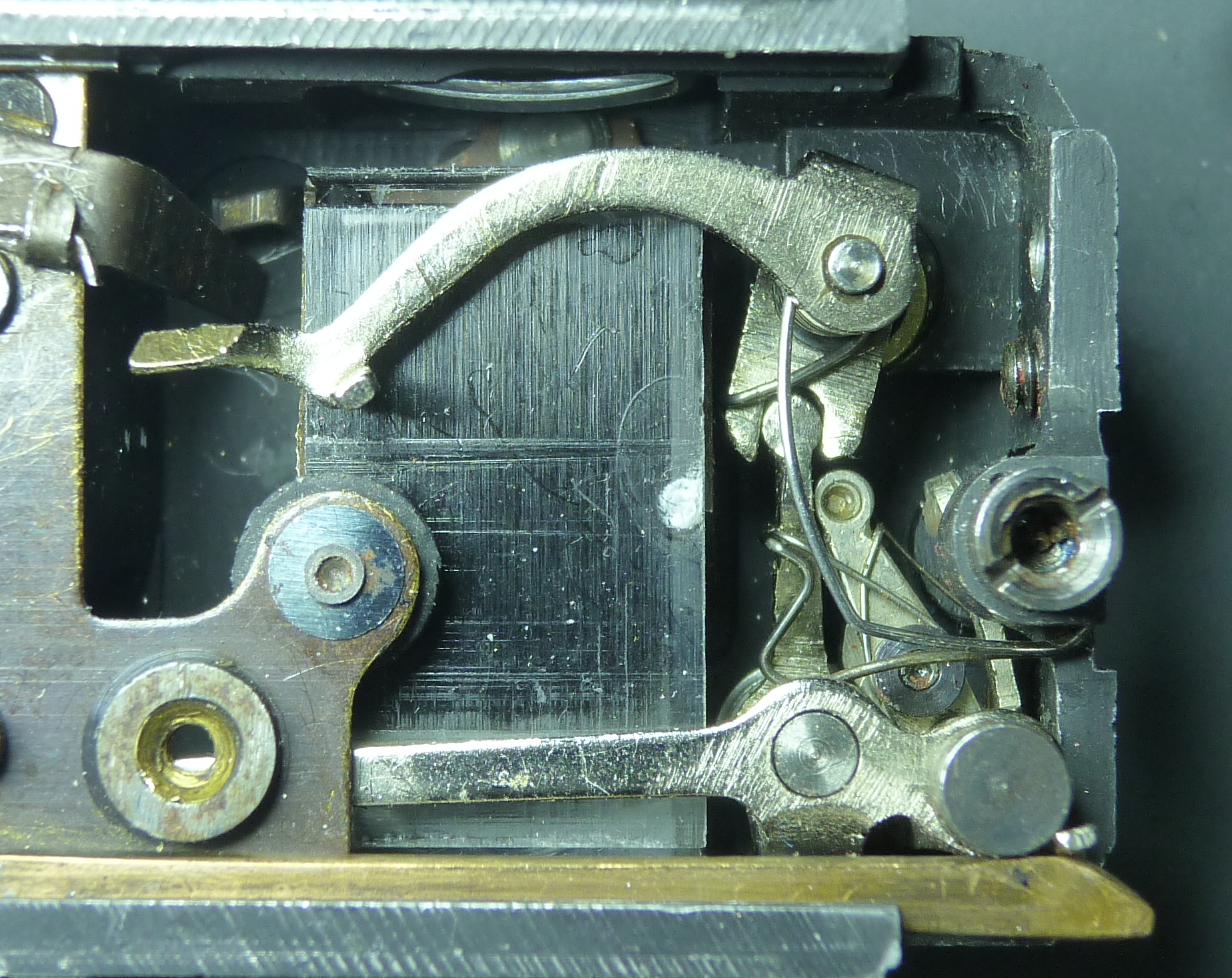
The end pieces of the escapement lever and the blade locking arm are clearly visible when the front plate is removed. In the image below, these are 4a and 4b.
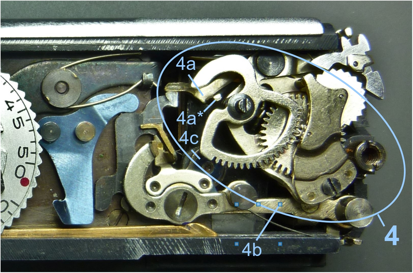
4a represents the outer end of the escapement lever, which is in contact with the release lever and is held by it until it is released. The end 4a* of this lever is only visible as a pin with which the lever is braked by the escapement.
Only the middle part of the blade locking arm 4b is visible. The end with the two blade pins can only be seen from the front (see image below) and the other part is covered by the escapement.
As we will see below, the lever 4a is accelerated with strong spring force after the shutter is released. The rubber buffer 4c brakes this movement at the end.
The found link
However, if you remove the escapement from the camera, disconnect the escapement lever, and reinstall it in the camera body, the connections become clear. The following image shows exactly this situation. But first, let’s take a moment to remind ourselves where we are in the Minox:
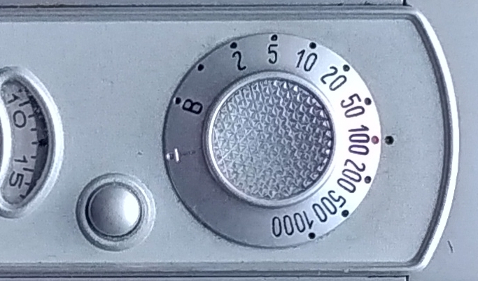
Minox front plate with shutter speed dial
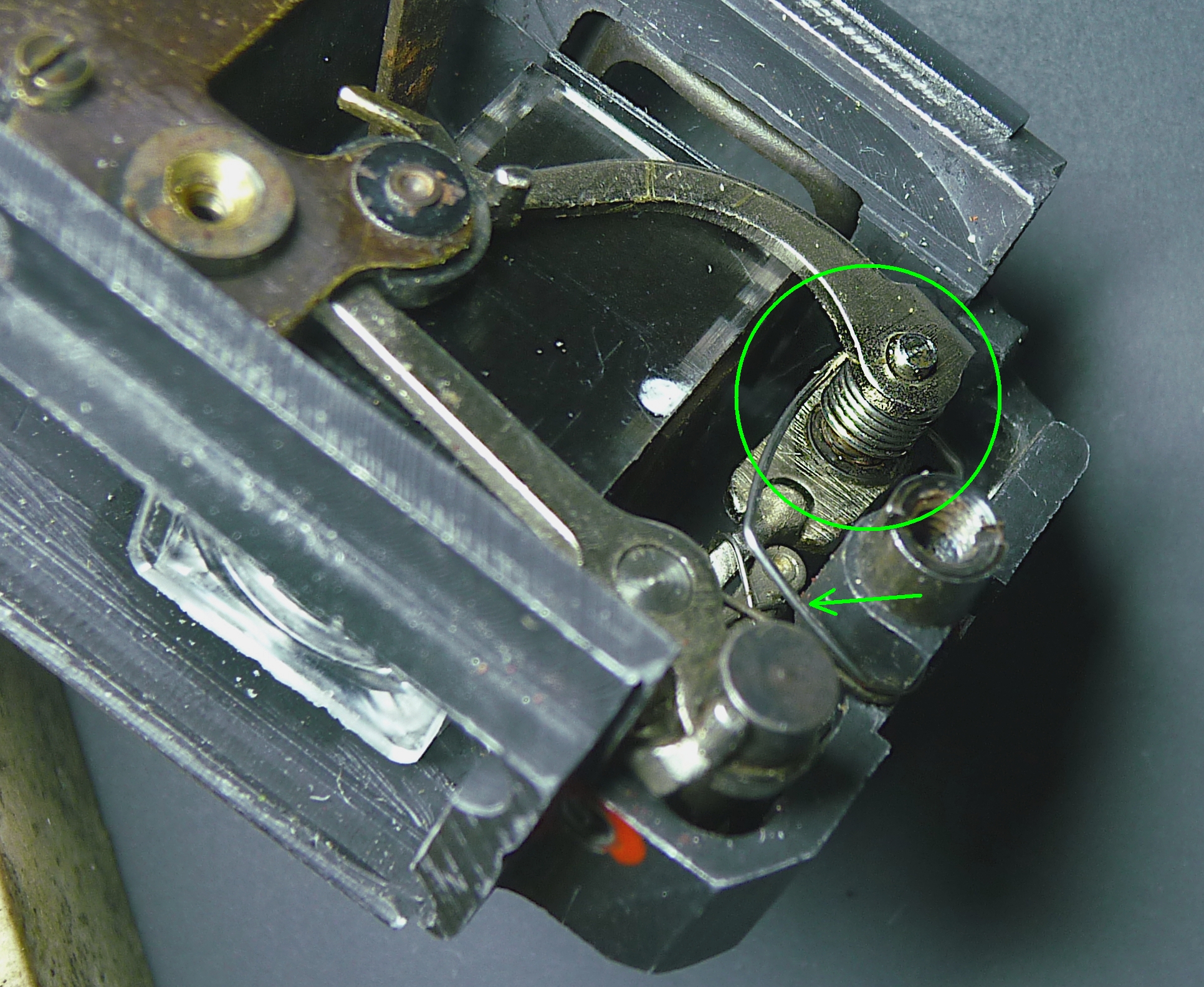
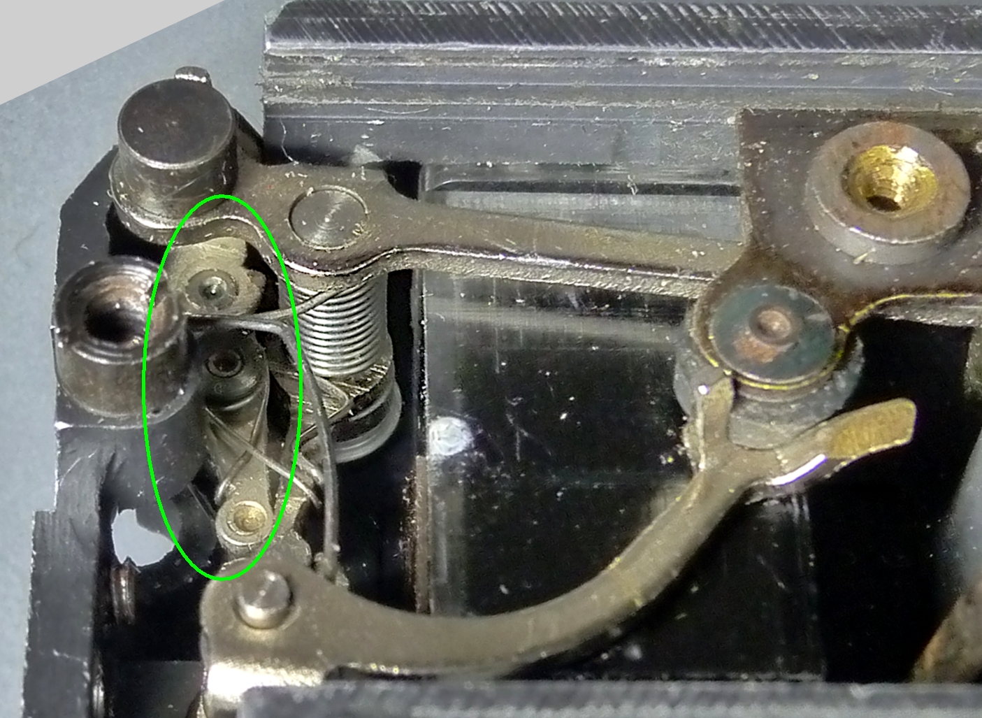
Here is the situation described above behind the front plate after removing the escapement:
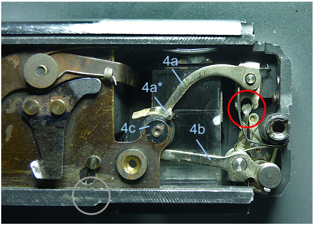
In the red circle we see the long-sought missing link. It is a kind of knee joint that connects components 4a and 4b. The shape and dimensions of both levers ensure that exactly the required speed of the blade locking pins is achieved.
The position shown corresponds to the final position after the exposure process. The end of the escapement lever 4a* has hit the rubber washer 4c which serves as brake, and the blade locking arm with the blade pins (grey circle, not visible) has completely retracted from the front of the camera.
In the video on the right you can see the kinematics of the knee joint during the cocking process.
The storage of drive energy
The Minox uses four springs as energy sources to drive the shutter. Two of these springs are used to directly drive the blades and are discussed in the relevant article. In addition, there are several springs for resetting and positioning individual components in the whole exposure system, which are not of interest to us here.
This article deals with the torsion springs of the two control levers.
The torsion springs
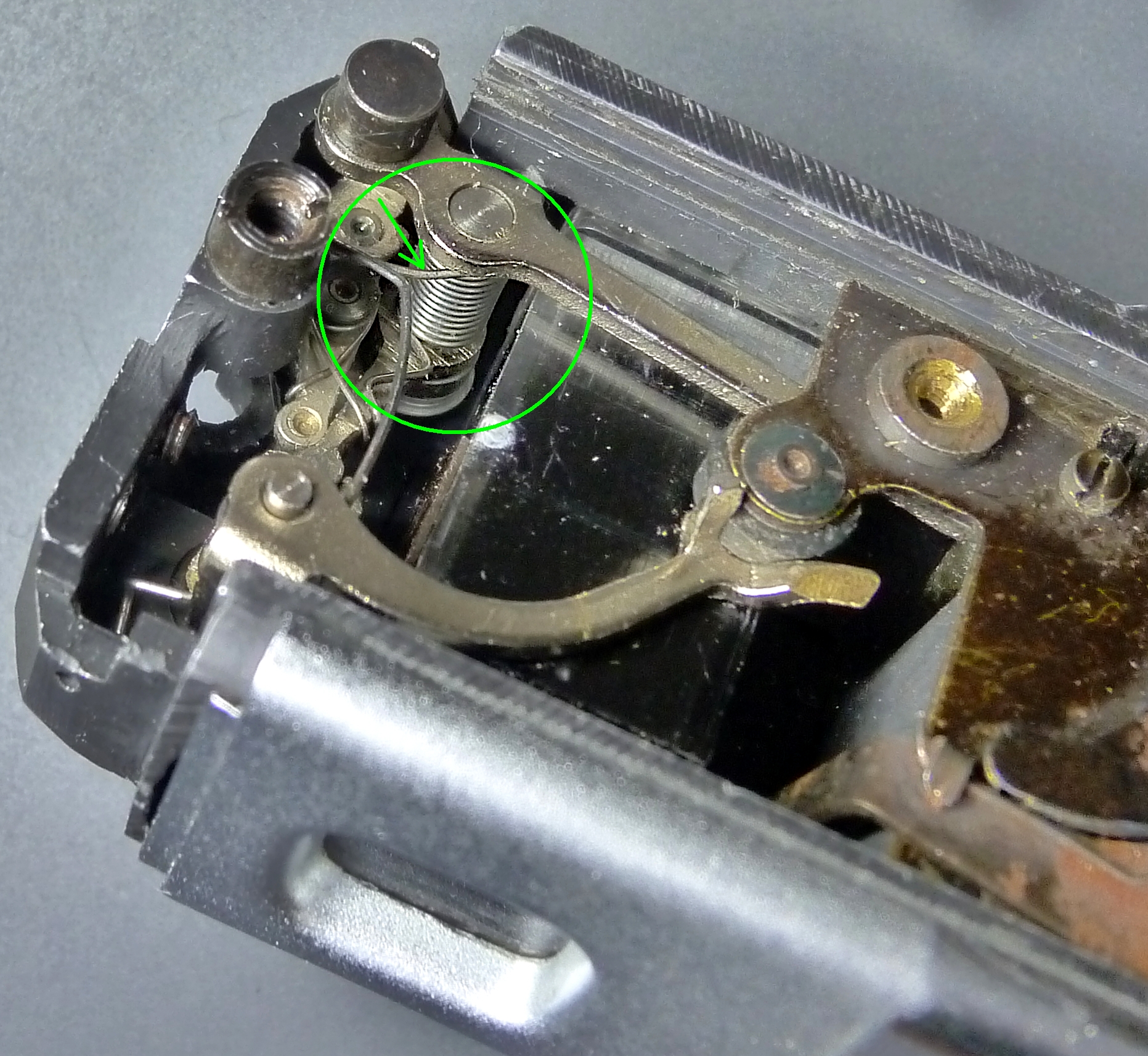
The following two images illustrate the installation of the springs. These are the two strongest springs within the Minox.
The torsion spring driving the escapement lever (picture above) also drives the escapment. This happens when the escapement lever presses its pin 3d onto the segment gear of the escapement. This wheel, in turn, drives the escapement gear, as can be seen in this short video.
The image above also clearly shows how the two levers interlock. At this point, the escapement lever specifies the correct pivot position of the blade locking arm at every moment of the shutter release process. No special pressure is required for this, as can be seen from the ratio of the lengths of the lever arms (see image before last). Therefore, no energy is transferred. This is not necessary, as the blade locking arm has its own drive spring:
The tension of the springs must be sufficient to achieve exactly the swivel speed specified by the escapement during the release process. Deviating speeds would result in incorrect exposure times. If anything, the levers could swing too slowly as a result of resined bearings. This would then result in exposure times that are too long. However, since the springs are strong and the required speed is rather low, this is unlikely to happen.
What conclusion can be drawn from this for maintenance purposes? The two springs and the bearings they enclose should be free of adhesions. However, if the shutter runs too slowly, other components in the Minox are probably to blame.
Cocking the springs
How are the springs cocked? This happens when the Minox is cocked, i.e. pushed together.
The spring hooking arm is firmly connected to the lower part of the housing. This brass part runs from the bottom to the very top inside the Minox.
When the Minox is pushed together, this brass rod inside the camera is pushed toward the viewfinder. There, at the top of the rod, our two springs are cocked.
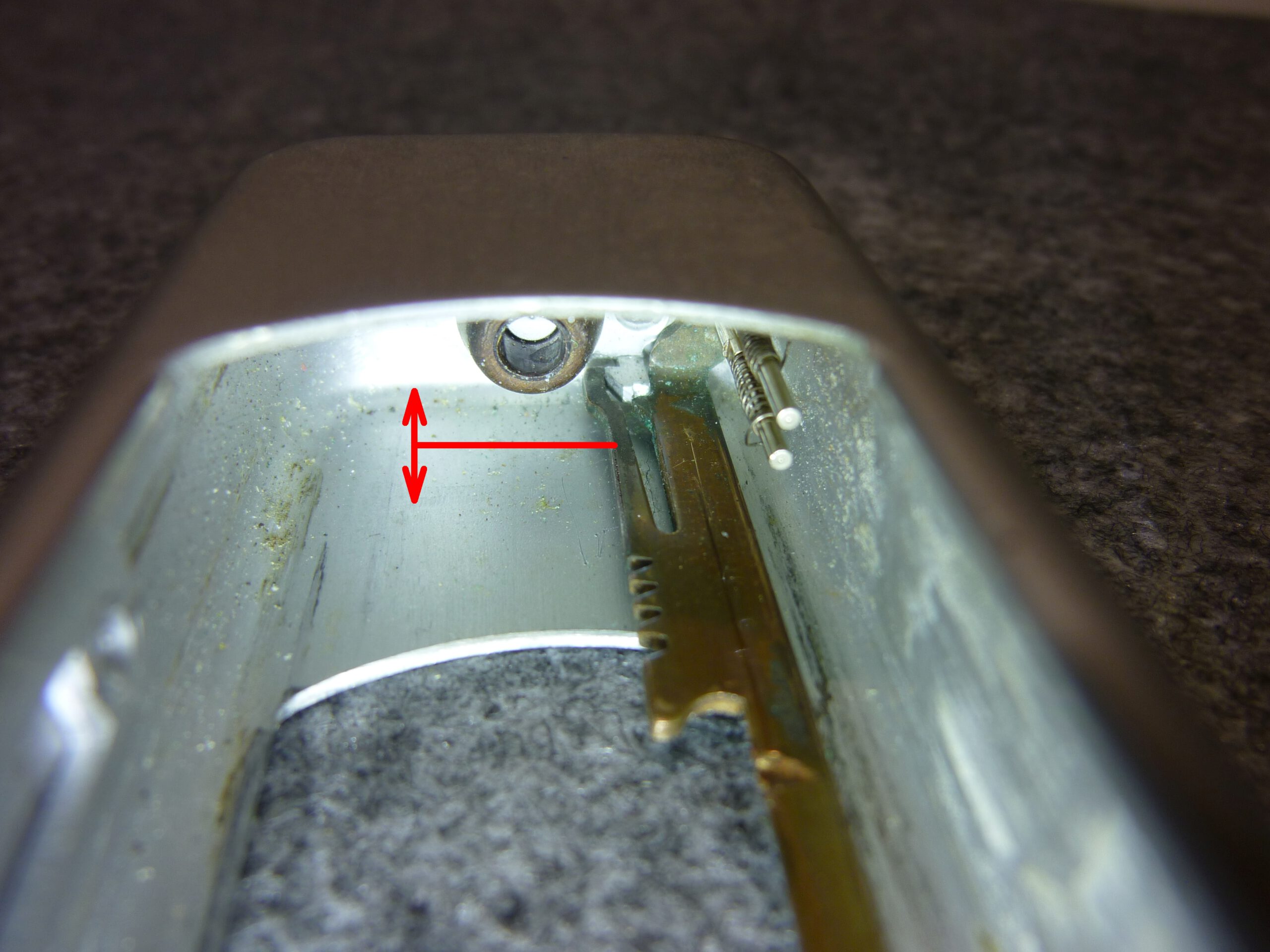
The spring hooking arm controls the entire cocking process, including the cocking of both torsion springs. To do this, its tip presses against the corresponding part of the blade locking arm, bringing both levers into their starting position. The following two images show the condition before and after the cocking process:
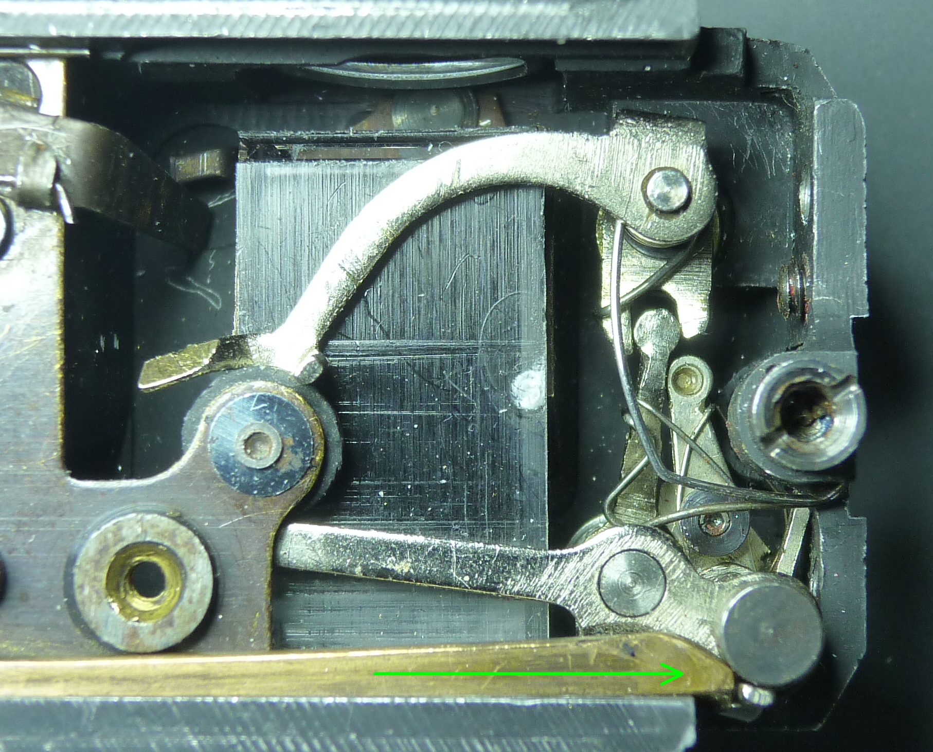
green arrow: movement of spring hooking arm
To better understand the sequence of movements, here is a short video of the same situation.
At the end of the cocking process, the left end of the escapement lever has locked with the trigger lever, and on the other side, the two pins of the blade locking arm engage with the blades and hold them in the starting position. This cannot be seen in the video because the trigger lever has been removed and the blades are only visible from the front of the camera.
Flash synchronization
From 1954 onwards, the Minox A III had a synchronized flash contact and is therefore referred to as A IIIs. This electrical switch is also operated by the blade control. It ensures that the flash bulb is fired in such a way that the full amount of light is available precisely when the shutter is fully open. You can find details in my article about the Minox AG-1 flash unit here.
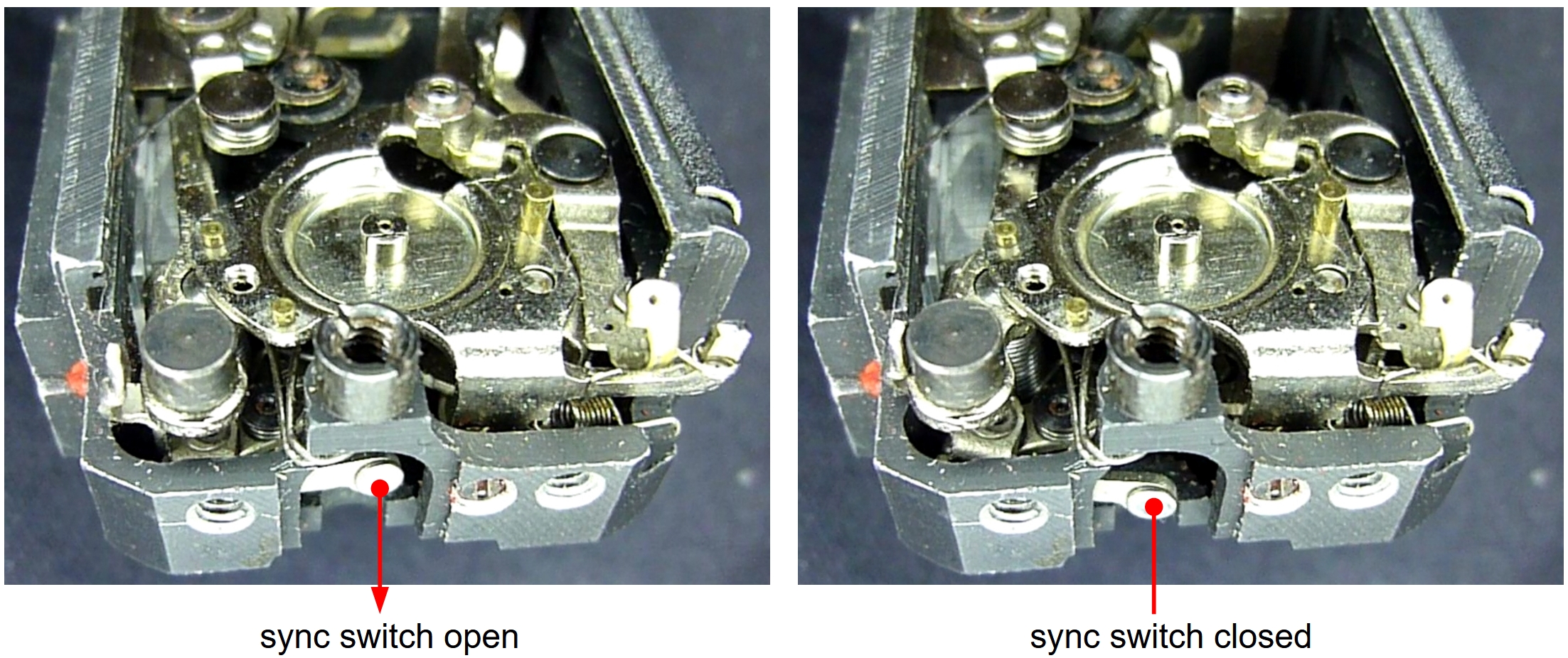
The following image shows the flash synchronization lever as seen from the right:
The flash synchronization lever is driven by the locking blade arm in such a way that its switch button describes a curved path that closes the contact at exactly the right moment.
The flash synchronization lever operates at all shutter speeds and closes the flash contact. However, connecting a flash unit only makes sense if you set the specified exposure time to 1/20 s or longer.
Summary
The blade control subsystem is the central mechanism of the Minox exposure system. It holds its own mechanical energy to perform its various tasks. It receives the time and speed information from the escapement. For long exposures, it receives its specifications directly from the shutter speed dial and from the user.
Go to the next article How the Minox shutter works
Back to the article The minox exposure system