The unknown modifications – uncovering the secrets inside a camera legend
What do we know – and what do we not know – about the early production period of this gem of the camera world? What problems appeared when the first production units were built, and how did the ingenious engineers of the time solve them?
The Curious Case of the Non-Existent Machined Slot
by Burkhard Fenner
For quite some time now, I have been interested in the VEF Minox Riga, and by now I have had the opportunity to look inside, clean, and repair quite a number of them. This unique time piece of the camera history still fascinates me so much today that I have shaky hands whenever I open one of them for the first time.
And, totally enchanted, I ask myself: What is new in this paticular camera? What parts am I going to see in there for the first time?
This subminiature camera is a masterpiece in its own right, engineered and put together by true masters of their trade.
From Prototype to Production – in Just 17 Months
Back in November 1936, shortly after he and his partner Richard Juergens signed the contract with VEF in Riga for the future production of the Minox subminiature camera, Walter Zapp moved from Reval in Estonia – today’s Tallinn – to Riga in Latvia. Not long before, he had successfully finished his first prototype of the Minox camera after a long and painstaking three years of new ideas, sketches, hand models, drawings, and the hand-building of a first working model. He was now eager to transfer this camera into full-scale mass production.
Apart from the usual work involved in bringing a product from the mock-up and prototype stage into full-scale manufacturing, he had a couple of new ideas he wanted to realize with the new production model. He also needed to change the film format from the original 6.5 × 9 mm to the 8 × 11 mm format, as agreed in the contract.
Changing the film format to 8 × 11 mm alone required an almost complete redesign of many components, including the most complex part: the camera lens, which also had to be completely recalculated. Some of the new features he wanted to include in the new Minox production model were a modified automatic compensation system for the film transport, further development of the escapement to include a 1/2-second shutter speed, and a sliding internal yellow filter. One of the changes Zapp himself wanted most in the transition to the production model was a newly designed viewfinder with a properly visible object frame and much less image distortion.
His direct contacts at VEF during this initial phase became a man named Eduard Petters and the designer Valters Grīnbergs, who later became head of the design team and was one of the people who enabled the transfer from prototyping into production within this very short period of time.
Within 17 months, by April 1938, the team around these three people was able to design the modified version of the camera with all its new features, hand-draw all the necessary manufacturing drawings for the camera and its accessories, design, draw, and manufacture most of the tooling required to manufacture each individual component of the camera, and begin production of the first production prototypes.
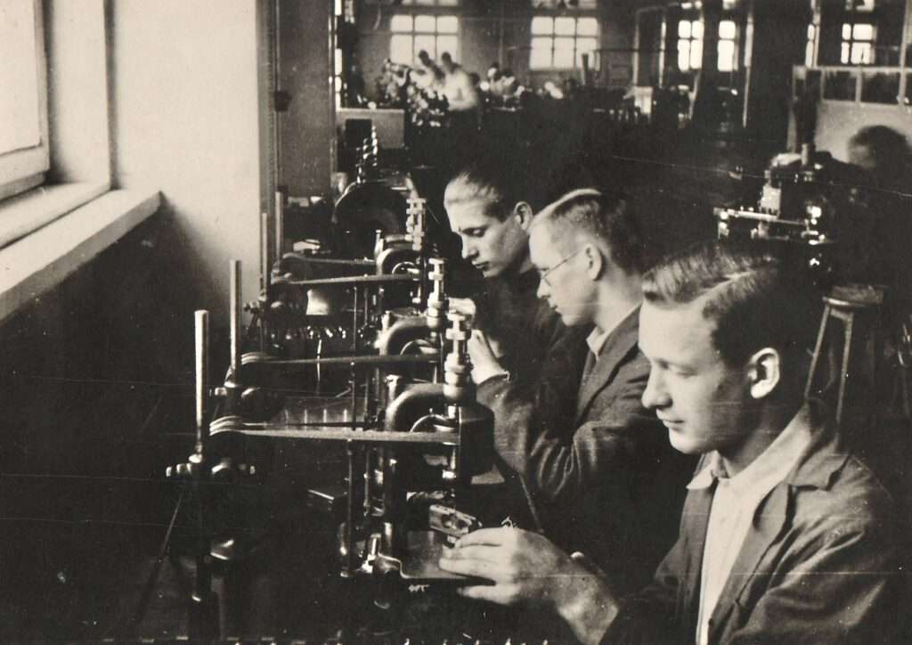
(With the kind permission of the Museum of VEF History, Riga, Latvia)
Even though this first period of bringing the Minox to production level appears to have been very short, it seems to have taken much longer than anticipated before full production could really begin and the planned numbers of cameras could be produced. The start of production was announced in the local news in April 1938, but it was not until November 1938 that the “first factory-produced” VEF Minox Riga was handed over to the Latvian President. It seems to have taken an additional, unexpected period of time – until around August 1939 – to bring production up to a reasonably satisfactory level of around 300-400 cameras per month.
One interesting piece of evidence supporting this “slow start” theory is the fact that only about 2,500 cameras, up to roughly serial number #03500, were built with the original 12-tooth film advance claw. One should know: that the serial numbers with VEF Minox cameras start with the first produced camera at serial number #01000 and at the beginning of the production the design indended a 12-tooth film transport claw and all cameras were equipped with such one.
Another evidence suggesting that the 12-tooth film advance claw was used until about serial number #03500 is a film showing different parts of the VEF Minox production. The film was produced by VEF in 1939, and I guess mid to end of that year. It shows parts of the camera assembly and there showing a camera with the serial number #03316 being equipped with a 12-tooth claw. Nowhere in the film the new designed 3-tooth claw could be spotted.
The subsequently used 3-tooth flat film advance claw must have been introduced around or after October 1939. This would mean that a total of roughly 2,500 cameras were built between April 1938 and October 1939. Considering a higher production output during the later months of this first production period until October 1939, this means that the early months of production must have had a very low output – or perhaps none at all.
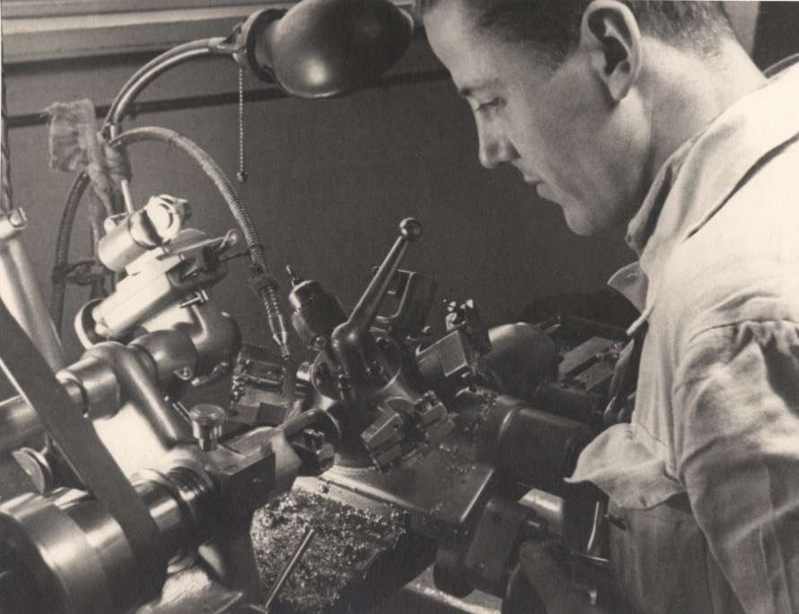
(With the kind permission of the Museum of VEF History, Riga, Latvia)
This is also understandable, especially when you consider the effort required to bring VEF – an electrotechnical and large industrial company that had never built a camera or any lenses – up to speed to manufacture all the required parts from scratch and entirely in-house. To make the lenses in-house, a complete optical department with a lens-grinding facility had to be built and set up, and the specialists operating it had to be trained. Similar efforts had to be made to manufacture the camera’s quite unique and strong stainless-steel housing in order to implement the demanding deep-drawing process required.
Another factor that probably contributed to the delays and slow start in manufacturing this masterpiece of camera engineering was, that during the rollout, small problems with certain functions or parts emerged and had to be rectified. Of course, there were also modifications to the design and individual parts later on, but by then these were made more with potential manufacturing cost savings in mind. One has to understand that the camera was always in the higher price segment, and therefore an ongoing effort to reduce production costs was underway.
Let us now have a look at one of these changes in detail.
But Something Was Wrong…
We already mentioned the 12-tooth film advance claw earlier in the article, which was modified to a 3-tooth flat film advance claw at a very early stage of production. As I also mentioned, we know today that only about 2,500 cameras were built with the 12-tooth claw, while all the remaining cameras were equipped with the 3-tooth flat claw. Even though only about 2,500 cameras were originally equipped with the 12-tooth version, it appears that quite a few of them were later modified – probably by the VEF factory itself or its representatives – with the newer more reliable 3-tooth flat claw.
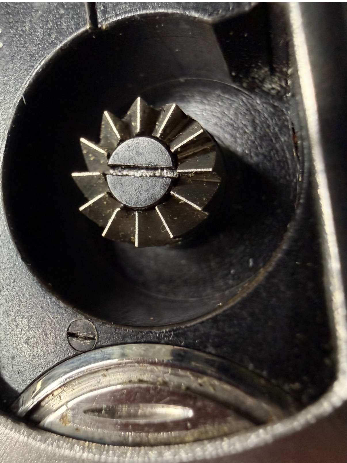
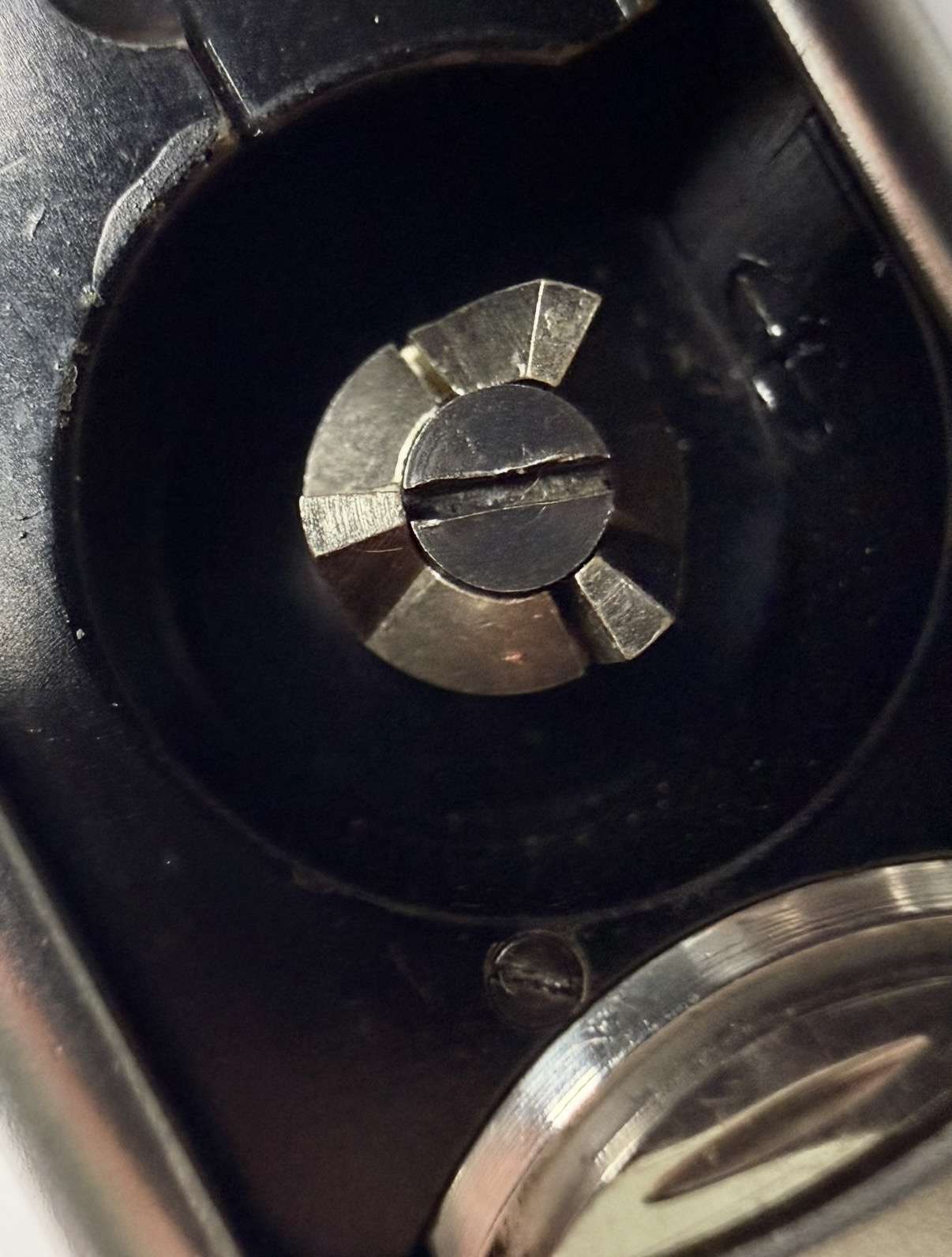
In addition, I assume that during the 1950s and 1960s quite a few more were modified again when serviced – probably by Minox GmbH or Minox Inc. and their representatives – using the then more modern Minox A type of 3-tooth sharp-style claw.
This means that considerably fewer than a total of 1500 units with the original claw ever remained on the market, and an even smaller number have survived. This fact makes them highly sought-after items today for collectors of VEF Minox Riga cameras.
But why was the 12-tooth claw changed to the 3-tooth flat claw in the first place?
The answer is simple. Practical tests, and probably also feedback from actual users of the camera, showed that there were problems with fitting the metal film cassettes easily into the film chamber and achieving proper engagement between the 12-tooth transport claw and the three teeth on the film spool of the cassette. The 12-tooth transport claw leaves only very narrow spaces between the individual teeth, which often caused the teeth of the film cassette to jump out of engagement. As a result, the film would not be transported by the correct distance, causing pictures to overlap.
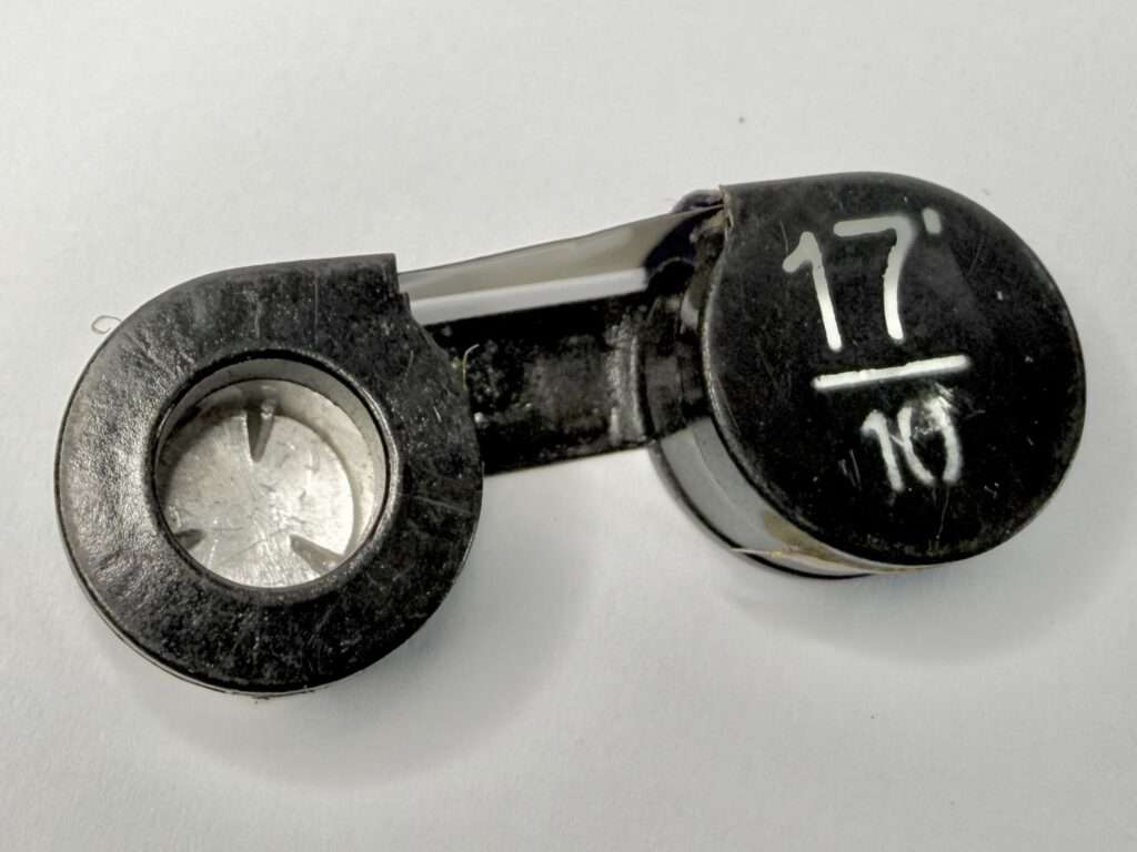
With the 3-tooth flat claw, this problem was solved, as the teeth of the film spool had enough space to engage properly. And because of the built-in spring clutch of the camera’s film transport system, any possible backlash in the system is irrelevant, as movement is permitted in only one direction.
This change from the 12-tooth to the new 3-tooth film transport claw was probably implemented—as the drawing of the 3-tooth claw also indicates—around the end of 1939, after the camera had been in production for around 18 months.
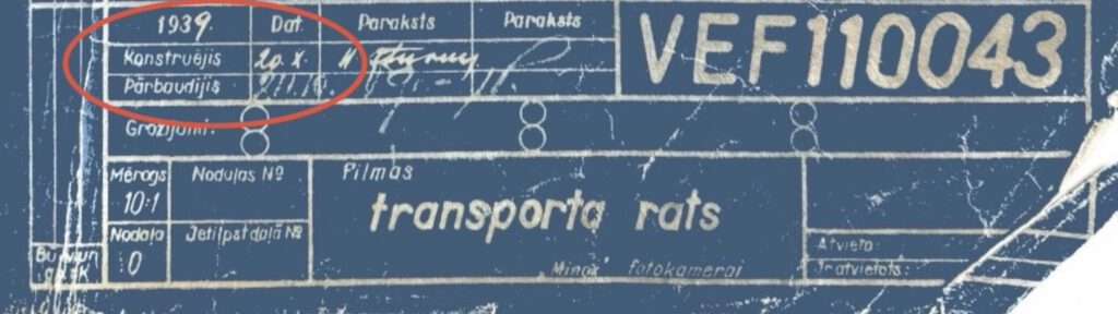
(With the kind permission of the Museum of VEF History, Riga, Latvia)
A Forgotten Document Provides the Answer
As I already mentioned in my earlier article „A COLD WAR ESPIONAGE AUCTION IN BEVERLY HILLS AND ITS AFTERMATH“ on the VEF testing tool for the film transport, I had the chance to visit the LATVIJAS FOTOGRĀFIJAS MUZEJS (Latvian Museum of Photography) in Riga. There, I was able to examine a document that discussed problems and their solutions during the initial production phase.
One of the problems referred to in this document was also the engagement of the 12-tooth claw. It reads:
"Transport gear 110043 is also fitted to this same gear segment assembly. The manufacturing of this gear posed no particular difficulties. The change here was made to the gear teeth themselves. There were 12 teeth intended for the gear. In practice, it turned out that ‘things did not go so well’, because difficulties arose when inserting the film cassette into the device: the teeth of the cassette’s inner cylinder had to mesh with the mentioned transport gear, which had these very narrow gear teeth. Because of this, the cassette teeth, of which there were only two, usually did not mesh between the gear teeth but partially rested on top of them. Even though the cassette was forced in, the meshing later disengaged and the transport no longer functioned. Now the gear has only three teeth, making it safe for the cassette teeth to enter freely between the gear teeth; and since rotation during film transport occurs in only one direction, gear backlash cannot have a disruptive effect here.

After milling the teeth, a slot is also cut in place of a tooth, into which the end of clutch spring 110061 is inserted, as it held better than in a hole and ensured transport operation.

In this connection, the bend at the end of the spring was also changed."
Unfortunately, this document itself was not dated, but the archive envelope said “end of 1930th,” which brings it roughly in line with the previously estimated period of modification.
There is one sentence that does not fully make sense to me, as it says: “Because of this, the cassette teeth, of which there were only two…” This would indicate that there were only two teeth inside the film cassette engaging with the film transport claw. I have never heard of any two-tooth film cassettes and know only the three-tooth ones that are common to this day. Two teeth would also not make much sense from a technical point of view, which suggests that this is simply a typing error in the report.
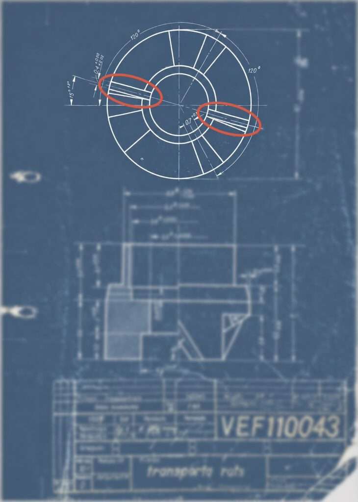
Interestingly, in the same part of the text, they also mention a slot that had been machined into the claw instead of a hole after the teeth were cut. This slot is something we actually know from both the 12-tooth claw and the later 3-tooth claw.
(With the kind permission of the Museum of VEF History, Riga, Latvia)
An Early Surviving Drawing Reveals Another Secret
During my visit to the VEF History Museum in Riga, I was able to see an early drawing of the 12-tooth film transport claw from January 1938, which showed only a hole in the underside of the claw and no slot at all on the top near the teeth.
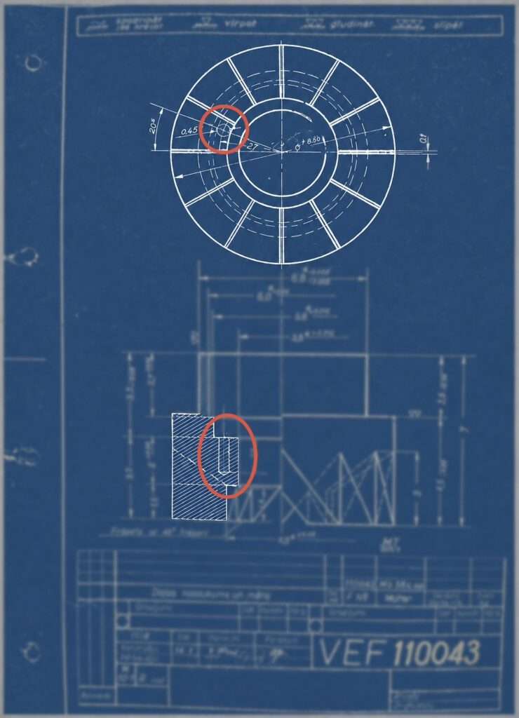
(With the kind permission of the Museum of VEF History, Riga, Latvia)
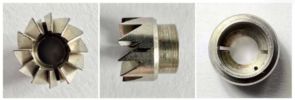
After checking many pictures of cameras with 12-tooth claws, I found that most of them appeared to have the slot, while with only one or two I could not determine exactly whether they had a slot or not.
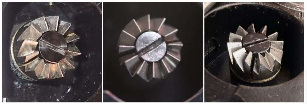
Luckily, I was able to get my hands on one of these cameras with an unslotted claw and could physically inspect this original, early and unmodified type of 12-tooth claw myself and in great detail.
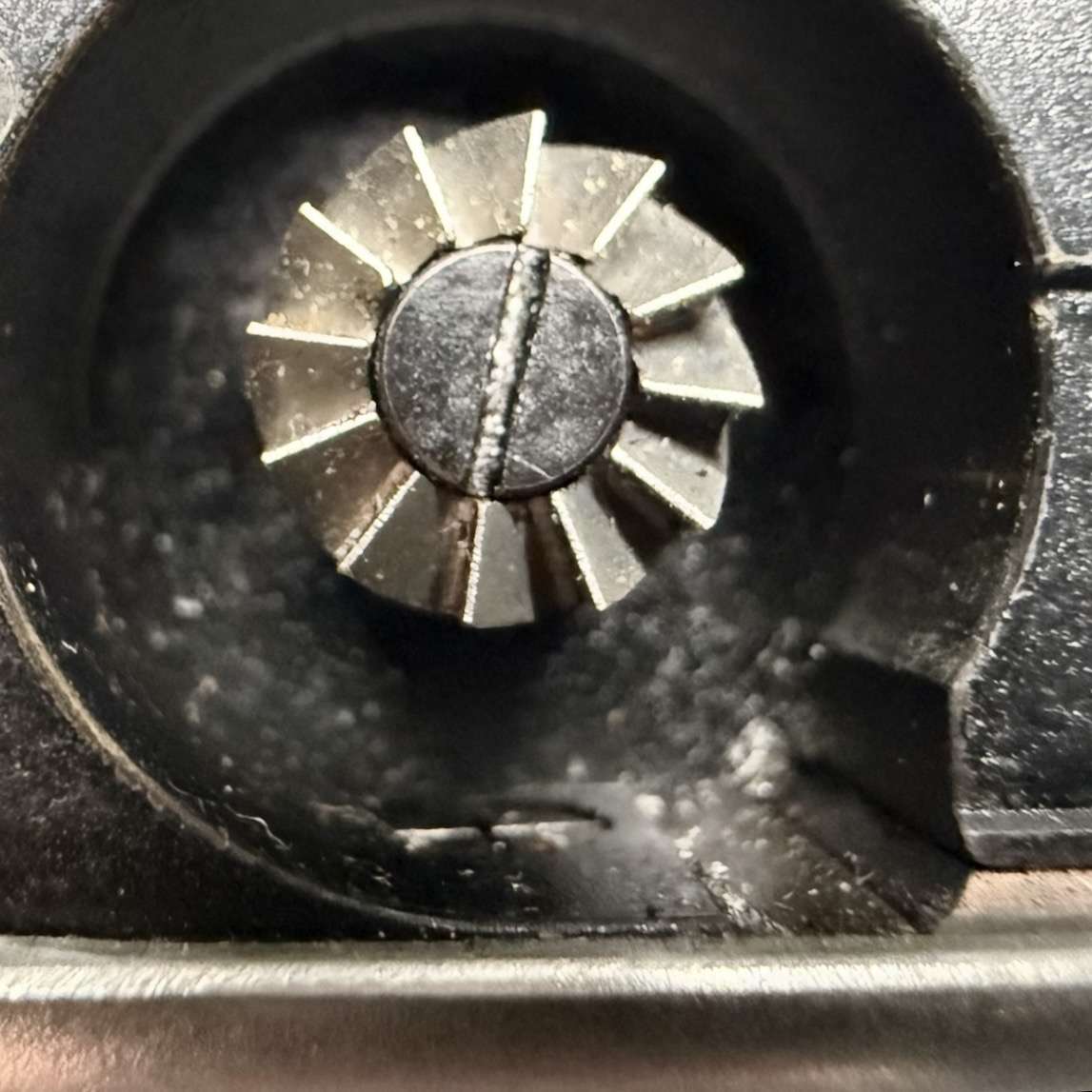
One could clearly see that there is no slot machined into the top surface of the claw, but when you turn it over, you can see only a small blind hole drilled into the body. This claw corresponded exactly to the one shown on the manufacturing drawing from January 1938.
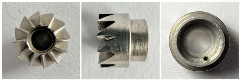
by Burkhard Fenner 2026
by Burkhard Fenner 2026
When I then compared this claw with the commonly known 12-tooth claw, the difference was clearly visible: the later version had an additional slot machined into the body. However, when inspecting the reverse side, one could also see that the later version still had the original small blind hole drilled in the same place. This would suggest that the additional slot machined into the claw was a later addition to the original design. I was also unable to find any drawing or other document concerning this early modification, and it seems that this alteration was made during the transition period leading up to the general change from the 12-tooth to the 3-tooth claw.
The Missing Milled Slot – and Why It Mattered
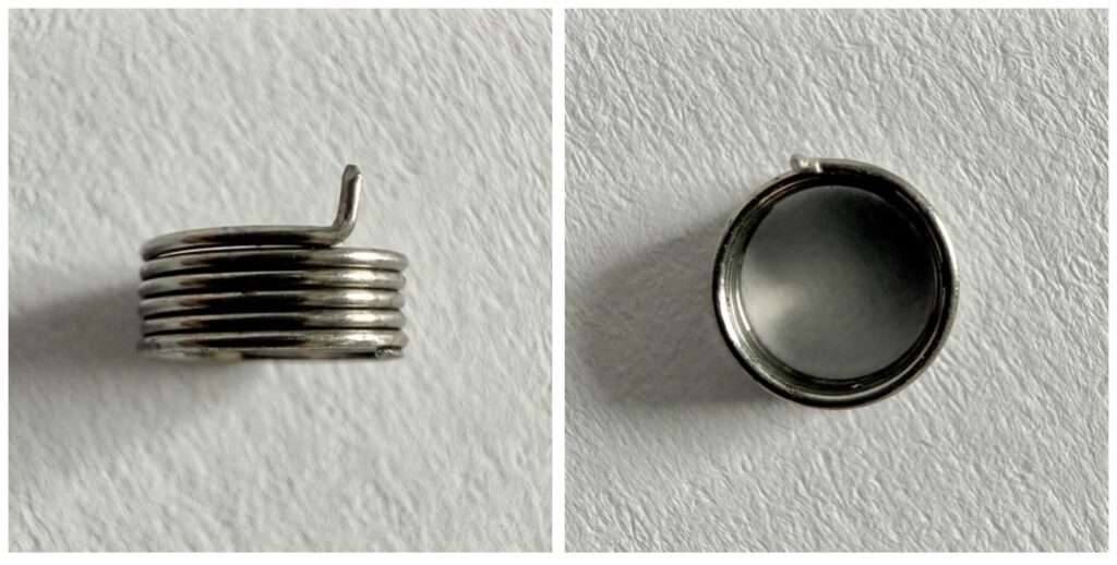
When I removed this early 12-tooth claw from the camera chassis and tried to disassemble it completely, I immediately understood why the modification involving the slot had been introduced at this intermediate stage. It took me a huge amount of time and patience to remove the small clutch spring from inside the claw, as a small projection on the spring was sitting tightly in the blind hole. While trying to pull it out, I was praying the entire time that the spring would not break and leave a tiny piece behind in the blind hole, which would have turned the whole 12-tooth claw into a piece of scrap.
As I know that these clutch springs have a tendency to break exactly at this particular stress point, I assume that the engineers at VEF had similar experiences and were forced to scrap quite a number of these expensive-to-manufacture 12-tooth claws. They therefore made this simple modification by adding the slot to the later 12-tooth claw. I also assume that during the first year or two, some of the original 12-tooth claws that had already been delivered with only the small blind hole were modified to the newer slotted version when the cameras were serviced at the factory.
This would also explain why a higher percentage of the slotted versions have survived, and why even some very early surviving VEF Minox Riga cameras already have the slotted version installed.
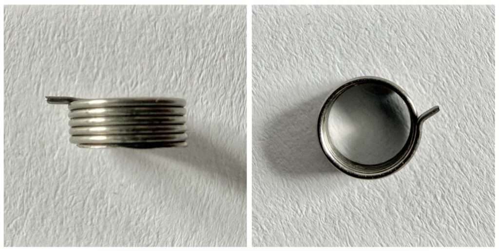
When the claw was modified with an additional slot, the clutch spring inside the claw also had to be modified. The upward-pointing projection on the early spring, which had originally sat in the blind hole, was now bent 90° away from the spring and inserted from underneath into the upper slot of the claw.
by Burkhard Fenner 2026
by Burkhard Fenner 2026
I hope I have been able to give you a good and detailed insight into one of the early production problems of this remarkable piece of photographic equipment and its very unique components. I also hope this helps you appreciate the rarity of some of its variants, which can still be found on the market today after having survived nearly 90 years of history with all its turmoils, and wars.
Reference:
Latvian Museum of Photography, Riga, Latvia
VEF History Museum, Riga, Latvia
Further articles on the VEF Minox Riga
- Restoration of a VEF Minox Riga: A unique description of a repair project with unique pictures and video of the inner workings of this camera by Burkhard Fenner
- If you are interested in the mechanics of the shutter on a VEF Minox Riga, you can find my detailed article on the subject here.
- Hans Schulz – The father of the VEF Minox lens? The first presentation of how the Minostigmat was developed in 1935 and by whom. Developing such a tiny lens was a technical triumph. And all of this was achieved without computer technology.
- Here I present my own VEF Minox Riga and its design principles.
- In 2024, I conducted a comparison of the two Minox lenses Minostigmat (VEF Minox Riga) and Complan (Minox A), which had never been done before. The results are presented here.