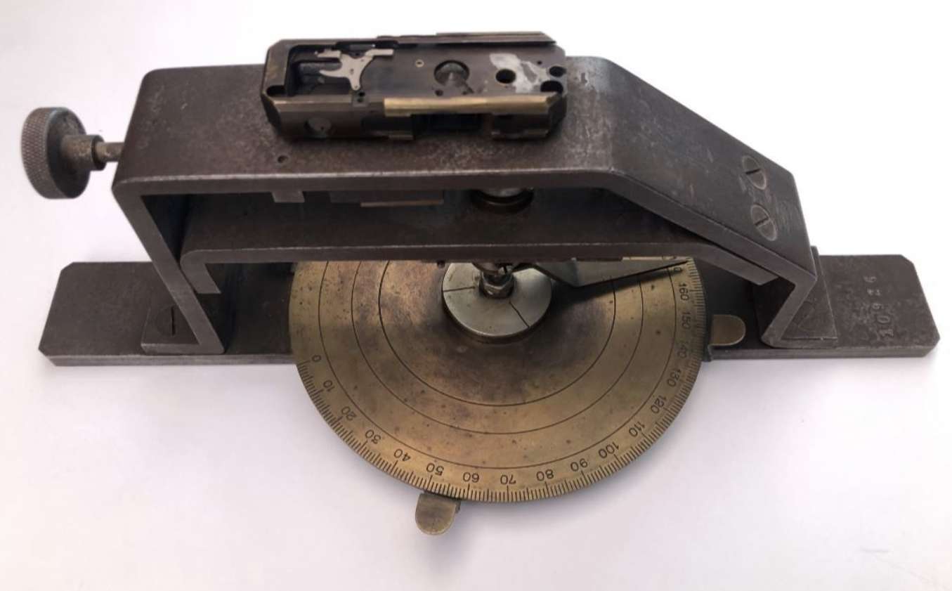
From ruined Minox films, a search for clues in the Baltic States, and the daring recreation of a VEF tool from 1938
By Burkhard Fenner
When I reported here last year on the complete restoration of a historic VEF Riga Minox, I also pointed out a film transport issue that only became apparent at the very end. However, what the article didn’t convey at all was the immense frustration I felt after developing the first roll of film from the camera. After all, I had already fully reassembled the camera and was looking forward to usable photos – only to end up with the shot below, featuring the overlapping images caused by insufficient film advance:
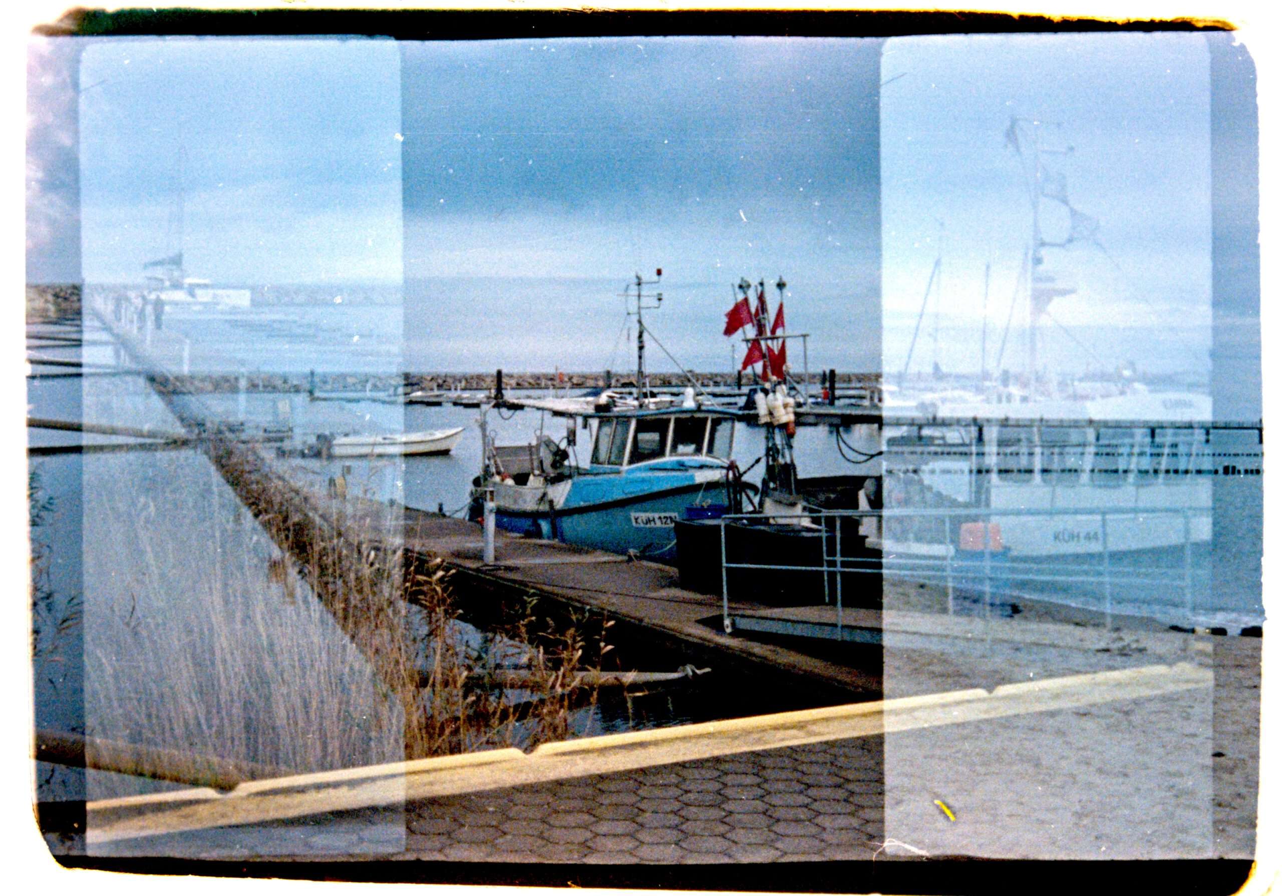
As I gradually realized, problems with correct film transport are not uncommon in the VEF Minox Riga camera. Various factors can cause this, and the issue highlighted in my article is just one of them.
The Tricky Nature of Minox Film Transport
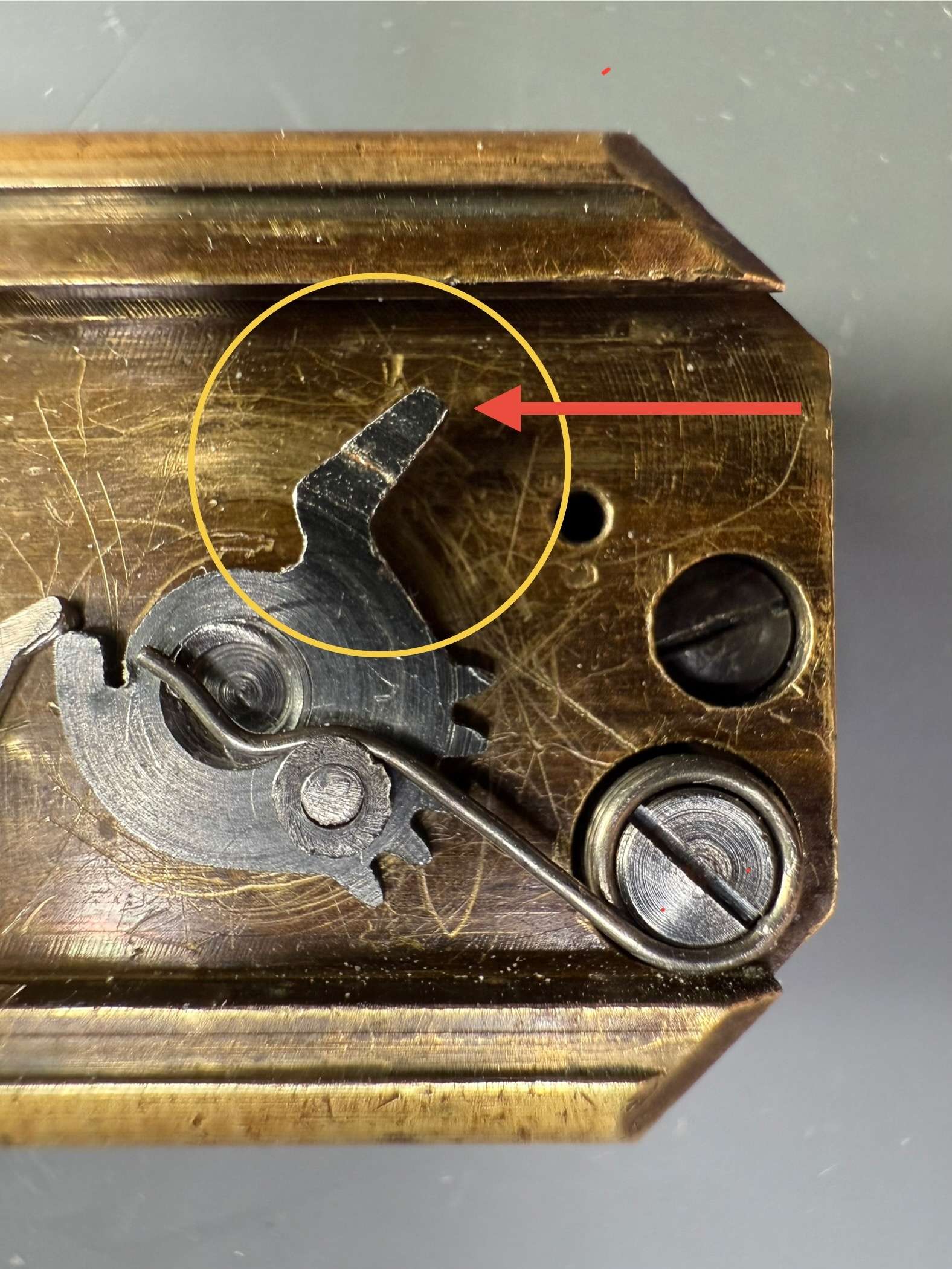
Correct film transport is crucial for a Minox; if a malfunction occurs, the spacing between frames on the exposed film becomes uneven, and in the worst-case scenario, the images can overlap.
While conventional cameras rely on film perforations to ensure consistent negative spacing, the Minox requires a complex mechanism to guarantee this.
This is a precision mechanical assembly where every component must work together with exacting accuracy.
After fixing the film transport issue, I naturally wanted to know as soon as possible whether I had succeeded. To avoid the need for a full film test at that stage, I devised two alternative methods:
- First, I glued a round cardboard disc onto the transport wheel and made an initial mark. I then advanced the film and made a second mark on the disc. The two marks formed an angle that could be measured. See here for details.
- To confirm the repair’s success with a different test, I sacrificed an old, unexposed roll of film and advanced it all the way through the camera. For each new frame counter reading, I placed a mark in the exposure window – on both the left and right sides of the film pressure plate – and labeled it with the corresponding frame number. The result is a complete picture of the individual frame positions on the film; any overlaps would be immediately visible. See here for details.
In Pursuit of the Original: Reconstructing a Historic Tool
I had no idea that, with my Method 1, I had reinvented an 88-year-old VEF factory secret. The very simple test setup I improvised out of necessity – using marked cardboard circles and measuring the resulting angles – turned out, in principle and much later, to be the absolute best solution to the problem.
To explain this fully, I need to provide a bit more background.
In August 2025, while searching the web for information on VEF Minox Riga cameras, I stumbled upon the website of Julien’s Auctions in California, USA1. This device had been auctioned there – in Beverly Hills, back in February 2021 – as part of a sale titled “The Cold War Relics Auction Featuring The KGB Espionage Museum Collection,” alongside many other interesting collector’s items.
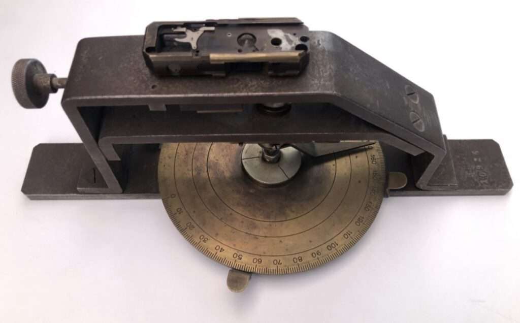
It was auctioned as Lot 190, listed as “Minox Riga Camera Accessories and Manual,” for $1,600 plus buyer’s premiums. The description read: “A collection of vintage Minox Riga camera items: photo album; two manuals; a receipt from 1951; half of an original box; a metal case; a leather bag; three film cartridges and an original film cartridge box; an original chamois cloth; and a rare factory diagnostic calibration device.”
Since I have always been interested in anything related to the VEF Minox Riga camera, I added the image of this intriguing diagnostic and calibration device to my small database under “VEF Minox Riga Tools.”
I later discovered that there had already been more interest in this device in the past; a short article about the tool had appeared on Julien Tanase’s website in December 20222. Like me, it seems he had simply saved the image and later wondered what the tool’s actual function was.
By sheer coincidence, almost a year later, I would discover the ingenious purpose served by that specific device used in VEF production. In mid-2026, I set out on a road trip around the Baltic Sea, and naturally, our route took us to the two birthplaces of the Minox camera: Tallinn in Estonia and Riga in Latvia. We arrived in Riga first, and I tried to gather as much information as possible about the origins of the VEF Minox camera.
After Walter Zapp had successfully completed the conceptualization, design, and construction of the first prototype – often referred to today as the “Ur-Minox” – in Reval (present-day Tallinn) during the late summer of 1936, he and his partner sought a suitable company to manufacture this groundbreaking invention. They found the ideal partner in the State Electrotechnical Factory (VEF) in Riga, which went on to manufacture the subminiature camera marketed worldwide as the VEF Minox Riga.
I had selected two museums in Riga as the starting points for my research into the origins and production of the VEF Minox: the Latvijas Fotogrāfijas Muzejs (Latvian Museum of Photography)3 and the VEF Vēstures Muzejs (VEF History Museum)4. While at the VEF History Museum, I was looking through a photo album documenting various specialized tools and devices from the VEF Minox Riga production era when I spotted this device. It was exactly the one I had kept on my computer for so long:
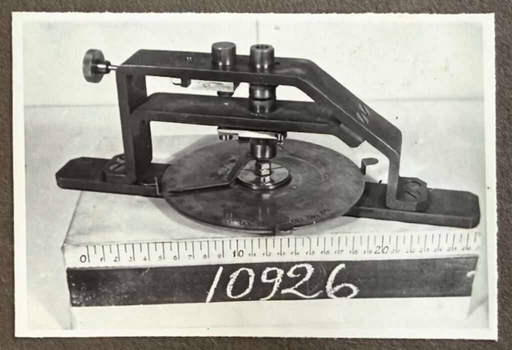
Even the part number – which, while not yet stamped onto the device in the old photo, was documented in the foreground – matched the number visible on the device from the auction:
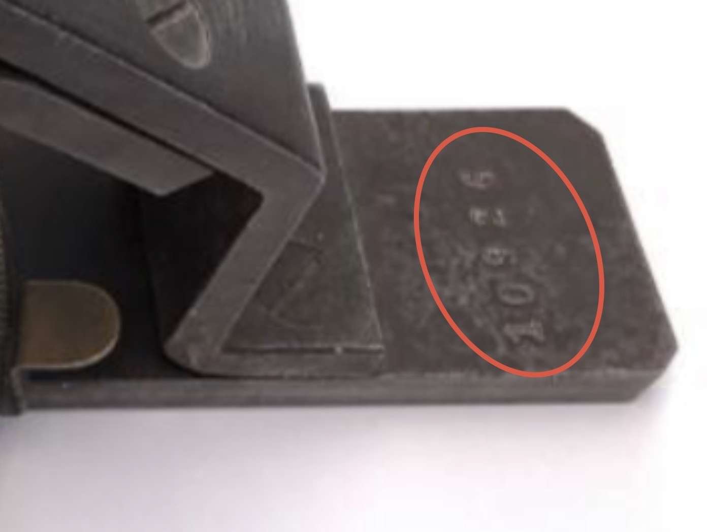
While I knew by then that the tool had indeed originated from the VEF Minox production line, I still didn’t know what it was actually used for. That would come to light later, quite by chance. I had the opportunity to examine a document at the Latvian Museum of Photography that detailed some of the challenges encountered during the launch of VEF Minox camera production.
To understand this, one must realize that the design and prototype – hand-crafted by Walter Zapp in Reval in 1936 – were not yet suitable for mass production; furthermore, several modifications he proposed needed to be incorporated into the VEF Minox Riga production model. In addition, complete production drawings for the camera had to be created, and specialized tooling had to be manufactured for the mass production of the camera’s components. Production began in April 1938 – after a mere 17 months, a timeframe that seems ambitious even by today’s standards. The document covered this production ramp-up and its problems.
I translated various passages of the document from Latvian, and one sentence in particular brought a smile to my face; it read – and I quote:
“The function of the custom-built transport mechanism was initially tested only using a fully assembled camera. It turned out that if there were unacceptable errors or deviations in the transport mechanism, almost the entire, fully assembled camera had to be taken apart to rectify the fault.”
I was all too familiar with this problem myself; I could instantly recall the beads of sweat on my brow when I had to disassemble my painstakingly assembled VEF Minox Riga yet again to locate and fix a fault. Things got interesting with the very next sentence:
“To avoid this, the function of the transport mechanisms is now tested right in the workshop using a special fixture.”
A brief description of the fixture followed, and I knew immediately which tool was being described.
“The teeth are located at the end of the gear belonging to transport mechanism 110043, which is mounted on an axle. A pointer is attached to the axle. A disc featuring circular graduations is mounted around the axle and can rotate freely; the disc’s zero point can be aligned with the pointer, and the disc locked in that position.
When the transport mechanism is operated, the pointer advances by a corresponding number of graduations with each revolution. This allows the uniformity of the transport to be assessed. The length of the arc traced by the pointer is proportional to the linear displacement of the transport mechanism. Since this ratio is known, the magnitude of the transport displacement can also be determined. Naturally, the transport operation is also verified in the laboratory by testing the finished camera with film.”
Incidentally, the “gear at the end of the transport mechanism” (part number 110043) is the film transport claw. It must therefore have been the “factory diagnostic calibration device” auctioned in 2021 – respectively the device shown in the photo album from the Museum of VEF History.
After returning from Riga, one thing was clear: a cardboard disc was no longer enough for me. I decided to build a replica of that historic VEF diagnostic device – using whatever I could find in my workshop.
My reconstructed calibration device
Back home with a new VEF Minox Riga on my workbench – disassembled for cleaning and repair – I recalled that ingenious device and our own simple, independent attempts to replicate that same testing procedure. Since I wanted to put more than just one VEF Minox Riga through this reliable testing process before final assembly, I decided to design and build a device that, while not identical in construction to the original, would perform the same function.
It was clear from the start that the build should cost next to nothing, look good, and be adaptable for future additional camera tests. So, the first step was to scour my scrap bins for potentially usable materials. I soon found a large brass ring from an old gas stove to serve as the base, along with some brass flat bars and a strip of flat iron to form the device’s main frame. A 2 mm brass plate I already had in stock and a store-bought 360° plastic protractor would serve as the measuring scale. Add some round stock for axles, plastic material for the camera mount, plus a few simple ball bearings, screws, and small hardware – all from my existing inventory – and I had all the necessary parts. The only thing missing was a counterpart for the camera’s film-advance claw. Soon, a low-cost solution for that came to mind: the small film spool from a broken plastic Minox film cartridge proved to be the perfect component.
All that remained was a great deal of sawing, filing, sanding, and brazing to create a brass framework for the device. The two camera mounts were turned from white plastic, and the black plastic spool from the film cartridge was fitted into one of them. Both were then attached to a flat steel bar.
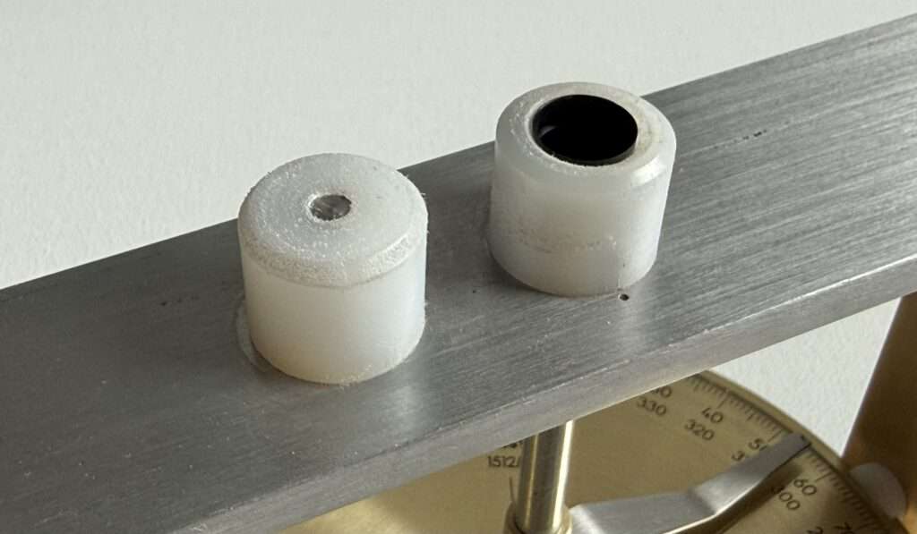
One of the mounts for the spool was screwed down firmly, while the second was designed to be adjustable – using a side screw and an elongated hole – to allow the camera to be clamped securely onto the fixture.
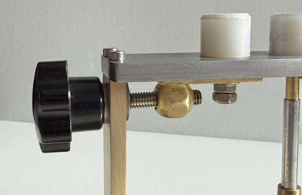
The plastic mounts ensure that the camera can be clamped in place without damage. A small ball bearing was embedded beneath the flat steel bar to receive a brass axle, which in turn was securely bonded to the plastic film spool. This allowed the direct rotary motion of the camera’s transport claw to be transferred to the device’s axle.
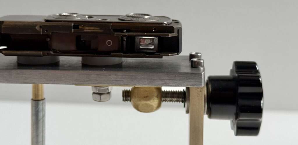
The axle was then extended using a screw-in attachment and guided through another ball bearing at the base of the device’s frame. Next, a larger ball bearing was pressed into the base plate from above, and a hollow threaded rod was firmly pressed into that bearing; this served as the mount for the angular measurement disc.
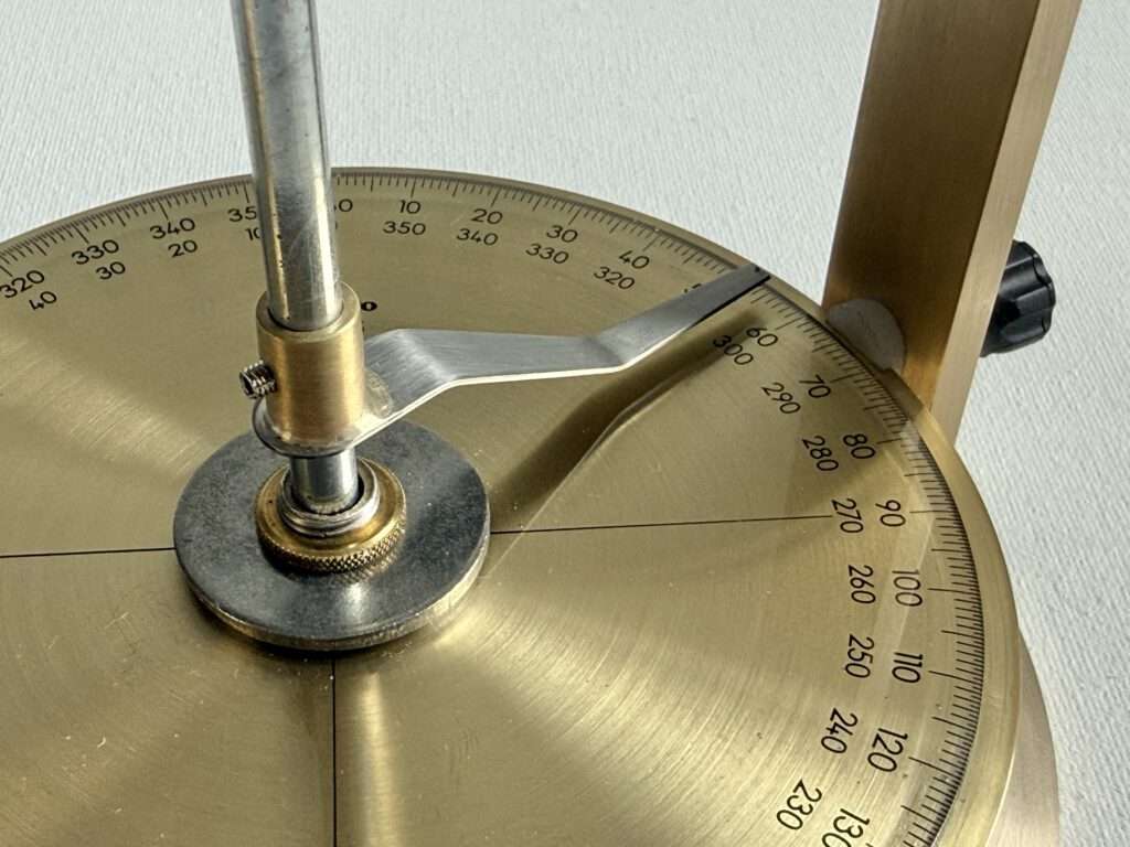
This component actually presented the biggest and “riskiest” challenge of the entire project, as I lacked a large lathe yet wanted to turn a rectangular 2 mm brass plate into a perfectly round disc. Consequently, I had to improvise by using an old drill, a longitudinal slide, and a small parting tool from my mini-lathe to transform the square shape into a round one. I certainly do not recommend this method and urge others not to attempt it. When I was about 0.5 mm away from cutting all the way through the metal, I threw in the towel and painstakingly cut out the blank using a fret saw instead. However, finishing and smoothing the surface afterwards proved to be quite manageable.
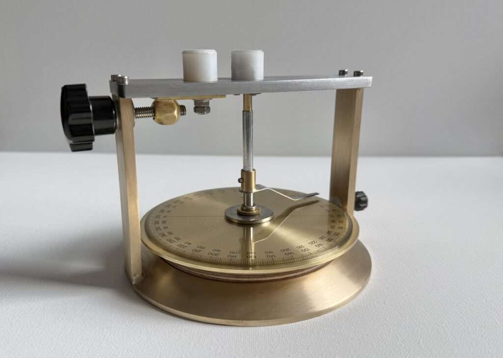
I bonded the plastic protractor to the sanded brass disc using a clear UV gel – the type used for mobile phone displays – and the result was impressive.
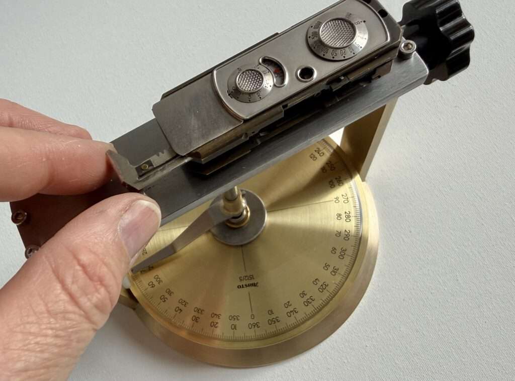
All that remained was the clamping mechanism for the measuring disc and the pointer to be attached to the rotating axis. A simple plastic clamping disc was designed for the clamp, pressing against the side of the measuring disc via a clamping screw. The pointer was cut from thin stainless steel (V2A) sheet, soldered to a bushing, sanded, and bent. Finally, all parts were given a final fine sanding and a light protective coating. Then came the assembly, initial testing, and the satisfaction of a successful project.
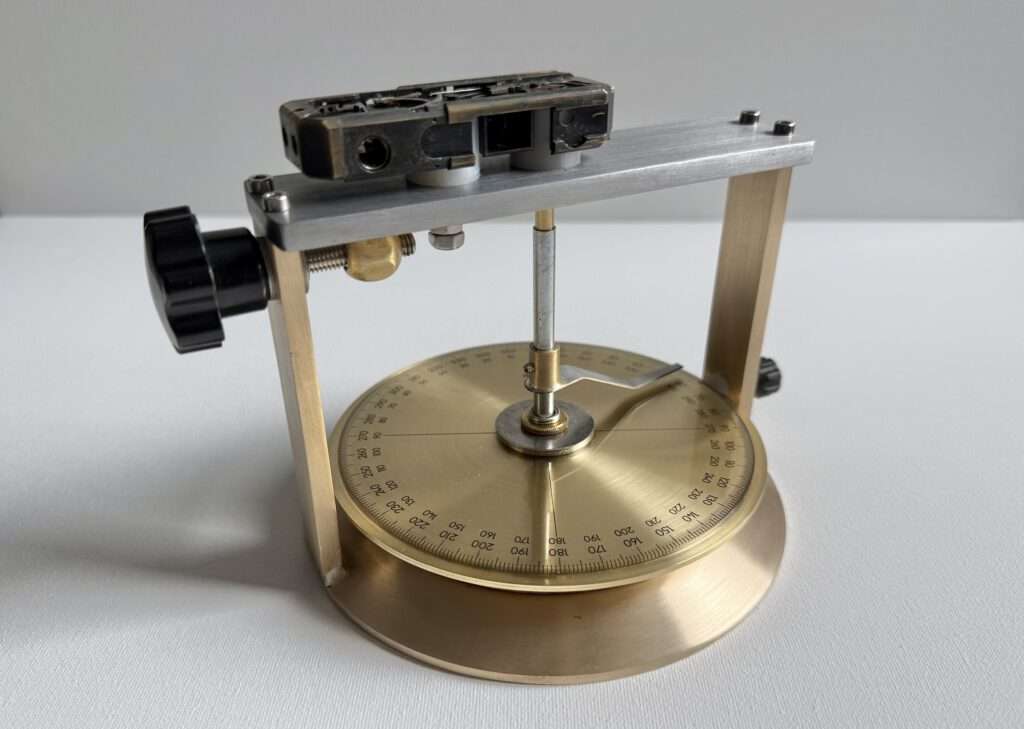
I think this device will be a huge help in fully testing key functions – such as the film transport – before assembling the camera, and will save me from breaking out in a cold sweat again.
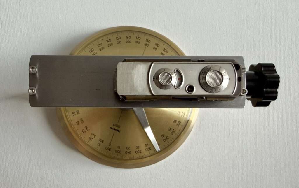
With the device, it is now possible to measure the maximum angle of rotation of the film transport system – approximately 130° – when the control panel is detached and the distance wheel (with exposure counter disc) is not installed; conversely, with the distance wheel (with exposure counter disc) and control panel installed, one can measure the full range of rotation angles corresponding to the numbers on the frame counter disc.
| frame counter | 1 | 25 | 36 | 50 |
| angle [degrees] | 130 | 115 | 100 | 92 |
Since this device provides an ideal and very stable mount for the camera for testing purposes, I would like to expand it over time and integrate additional testing functions for the VEF Minox Riga.
References
- https://www.juliensauctions.com/en/items/67765/minox-riga-camera-accessories-and-manual ↩︎
- https://juliantanase.com/vef-minox-calibrating-machine/ ↩︎
- https://www.rigamuz.lv/lfm/ ↩︎
- https://www.vefkp.lv/en/par-muzeju/ ↩︎
Further articles on the VEF Minox Riga
- Restoration of a VEF Minox Riga: A unique description of a repair project with unique pictures and video of the inner workings of this camera by Burkhard Fenner
- If you are interested in the mechanics of the shutter on a VEF Minox Riga, you can find my detailed article on the subject here.
- Hans Schulz – The father of the VEF Minox lens? The first presentation of how the Minostigmat was developed in 1935 and by whom. Developing such a tiny lens was a technical triumph. And all of this was achieved without computer technology.
- Here I present my own VEF Minox Riga and its design principles.
- In 2024, I conducted a comparison of the two Minox lenses Minostigmat (VEF Minox Riga) and Complan (Minox A), which had never been done before. The results are presented here.